background image

3  Checking Firmware Version

SMA Solar Technology AG

10

STPTL10-SBTL20-Display-AT-SG-de_en-12

Service Manual

3  Checking Firmware Version

The new display may only be installed on the following inverters and works with inverters with the 
indicated (or later) firmware versions.

• Determine the firmware version installed on the inverter. Use a communication product to access 

the firmware version; it will show you the complete firmware version.
If the firmware version on the inverter is lower than specified in the table, update the inverter's 
firmware to the specified firmware version or a later one. Perform the firmware update with an 
SD memory card or with a communication product (for detailed information about firmware 
updates, see the technical description "Firmware Update with SD Memory Card"; for detailed 
information about changing parameters, see the manual for the communication product at 
www.SMA-Solar.com).

4  Replacing the Display (SB xx00TL-20 and 

STP xx000TL-10)

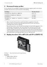
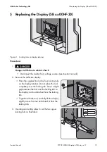
Figure 1: Locking tabs on display retainer

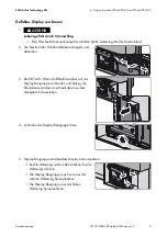
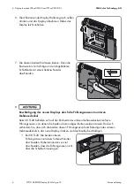
Procedure:

• Remove the defective display.
• Install the new display.

Device type

Firmware version

SB 2000HF-30 / 2500HF-30 / 3000HF-30

2.54.11.R

SB 3000TL-20 / 4000TL-20 / 5000TL-20

3.20.05.R

SB 3600TL-20

3.25.05.R

STP 8000TL-10 / 10000TL-10 / 12000TL-10 / 15000TL-10 / 
17000TL-10

2.60.08.R

Summary of Contents for STP 15000TL-10

Page 1: ...n Bauteilen des Wechselrichters anliegt Das Ber hren der DC Leiter oder der spannungsf hrenden Bauteile kann lebensgef hrliche Stromschl ge verursachen Alle Arbeiten am Wechselrichter d rfen ausschlie...

Page 2: ...den Wechselrichter mit der genannten oder einer h heren Firmware Version ausstatten Dazu Firmware Update mit SD Karte oder Firmware Update mit einem Kommunikationsprodukt durchf hren ausf hrliche Inf...

Page 3: ...anden und belegt die Klemmleiste mit dem Anschlusskabel aus dem Steckplatz herausziehen 4 Schraube der Display Baugruppe l sen 5 Display Baugruppe mit defektem Display herausnehmen Rechte Halterung na...

Page 4: ...hneiden 8 Besch digung des neuen Displays durch die F hrungsnasen im unteren Geh usedeckel Beim SB TL 20 befinden sich auf der R ckseite des unteren Geh usedeckels mehrere F hrungsnasen von denen die...

Page 5: ...em neuen Display einbauen Die Display Baugruppe in die linke Halterung einf hren Rechte Halterung nach au en dr cken und Display Baugruppe in recht Halterung einf hren Die Display Baugruppe in die bei...

Page 6: ...y AG 6 STPTL10 SBTL20 Display AT SG de_en 12 Serviceanleitung 7 Bei SB TL 20 Wenn Multifunktionsrelais auf der Display Baugruppe vorhanden war die Klemmleiste wieder auf den Steckplatz stecken 8 Wechs...

Page 7: ...ng stecken Dabei das Werkzeug nicht komplett auf die Rastnase stecken Zwischen Werkzeug und Rastnase muss etwas Luft bleiben damit das Display von der Rastnase gel st werden kann Display vorsichtig an...

Page 8: ...Sinne der EG Richtlinien 2004 108 EG Elektromagnetische Vertr glichkeit EMV 2006 95 EG Niederspannung NSR 1999 5 EU Radio und Telekommunikation Terminal Equipment R TTE Hiermit erkl rt SMA Solar Tech...

Page 9: ...which is present in the DC conductors and the live components of the inverter Touching the DC conductors or the live components can lead to lethal electric shocks All work on the inverter must be carr...

Page 10: ...rmware to the specified firmware version or a later one Perform the firmware update with an SD memory card or with a communication product for detailed information about firmware updates see the techn...

Page 11: ...n the display assembly pull the connecting terminal plate with the cable out of the receptacle 4 Loosen the display assembly screw 5 Remove the display assembly with the defective display Press the ri...

Page 12: ...e locking tab with diagonal cutting pliers as illustrated 8 Damage to new display by the keys in the lower enclosure lid 0 On the SB TL 20 there are several keys on the rear side of the lower enclosur...

Page 13: ...bly with the new display Slide the display assembly into the left hand retainer Press the right hand retainer outwards and insert the display assembly into the right hand retainer Press the display as...

Page 14: ...10 SMA Solar Technology AG 14 STPTL10 SBTL20 Display AT SG de_en 12 Service Manual 7 For SB TL 20 If a multifunction relay was present on the display assembly reattach the connecting terminal plate to...

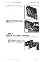
Page 15: ...abs on the display retainer Do not place the tool completely over the locking tab Leave a slight gap between the tool and the locking tab so the display can be detached from the locking tab Together w...

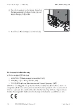
Page 16: ...e meaning of EC directives 2004 108 EC electromagnetic compatibility EMC 2006 95 EC Low Voltage Directive LVD 1999 5 EC Radio and Telecommunications Terminal Equipment R TTE SMA Solar Technology AG he...

Reviews: