5 Removing the BFS Assembly
SMA Solar Technology AG
Replacement Manual
STP50-4x-BFS-RM-xx-11
14
Position
Designation
A
AC switch, only included in STP 50-US-40, STP 33-US-41, STP 50-US-41 and
STP 62-US-41
Procedure:
1. Disconnect the inverter from all voltage sources (see Section 4, page 11).
2. Wait 5 minutes. This will ensure that the capacitors are discharged.
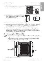
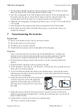
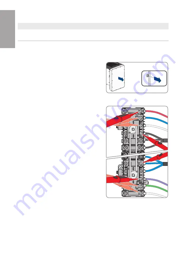
3. Release (TX25) all 10 screws of the enclosure lid of
the DC-Connection Unit and remove the enclosure
lid carefully towards the front.
10x
4. Discharge the DC Connection Unit at the contact points using a voltage detector without
intrinsic voltage source: Ensure that the residual voltage is less than 5 V.
5. On the right-hand side of the DC switch, each pair
of contacts DC+ against each contact DC- (red, blue
and white conductor against 1 black conductor;
gray, green and lilac conductor against 1 blue
conductor).
ENGLISH
Summary of Contents for STP 33-US-41
Page 57: ...1 SMA Solar Technology AG STP50 4x BFS RM xx 11 57 1 5 1 6 X703 1 X703 6 10...
Page 60: ...2 SMA Solar Technology AG STP50 4x BFS RM xx 11 60 DC DC DC DC 5...
Page 61: ...2 SMA Solar Technology AG STP50 4x BFS RM xx 11 61 AC DC DC AC DC 1000 V...
Page 62: ...2 SMA Solar Technology AG STP50 4x BFS RM xx 11 62 DC 5 C v v...
Page 67: ...5 BFS SMA Solar Technology AG STP50 4x BFS RM xx 11 67 5 DC DC DC 1 1 6 DC DC DC 7 8 X1...
Page 196: ...1 SMA Solar Technology AG STP50 4x BFS RM xx 11 196 1 5 1 6 X703 1 X703 6 10 WCtlHz Hz...
Page 198: ...2 SMA Solar Technology AG STP50 4x BFS RM xx 11 198 2 2 5 DC DC DC DC DC...
Page 199: ...2 SMA Solar Technology AG STP50 4x BFS RM xx 11 199 5 AC DC DC AC...
Page 200: ...2 SMA Solar Technology AG STP50 4x BFS RM xx 11 200 DC 1000 V DC 5 C...
Page 205: ...5 BFS SMA Solar Technology AG STP50 4x BFS RM xx 11 205 5 DC DC DC 1 1 6 DC DC DC 1 7 8 X1...
Page 211: ......
Page 212: ...www SMA Solar com...


