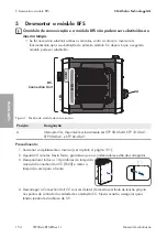
5 Desmontar o módulo BFS
SMA Solar Technology AG
Manual de substituição
STP50-4x-BFS-RM-xx-11
155
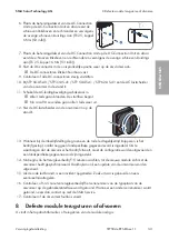
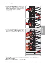
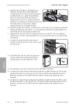
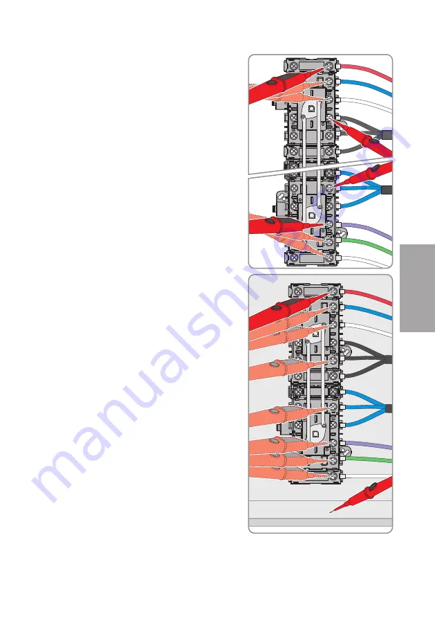
5. No lado direito do interruptor CC, cada par dos
contactos CC+ a cada contacto CC- (o condutor
vermelho, azul e branco a 1 condutor preto, bem
como o condutor cinzento, verde e lilás a 1
condutor azul).
6. No lado direito do interruptor CC, cada contacto
CC+ e CC- a PE (os condutores vermelho, azul,
branco , preto, cinzento, verde, lilás e azul a PE).
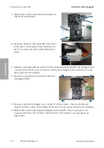
7. Efetuar a ligação à terra antes de substituir o módulo, de modo a evitar danos devido a
descargas eletrostáticas.
8. Remover a abraçadeira no ferrite do cabo plano
X1
.
PORTUGUÊS
Summary of Contents for STP 33-US-41
Page 57: ...1 SMA Solar Technology AG STP50 4x BFS RM xx 11 57 1 5 1 6 X703 1 X703 6 10...
Page 60: ...2 SMA Solar Technology AG STP50 4x BFS RM xx 11 60 DC DC DC DC 5...
Page 61: ...2 SMA Solar Technology AG STP50 4x BFS RM xx 11 61 AC DC DC AC DC 1000 V...
Page 62: ...2 SMA Solar Technology AG STP50 4x BFS RM xx 11 62 DC 5 C v v...
Page 67: ...5 BFS SMA Solar Technology AG STP50 4x BFS RM xx 11 67 5 DC DC DC 1 1 6 DC DC DC 7 8 X1...
Page 196: ...1 SMA Solar Technology AG STP50 4x BFS RM xx 11 196 1 5 1 6 X703 1 X703 6 10 WCtlHz Hz...
Page 198: ...2 SMA Solar Technology AG STP50 4x BFS RM xx 11 198 2 2 5 DC DC DC DC DC...
Page 199: ...2 SMA Solar Technology AG STP50 4x BFS RM xx 11 199 5 AC DC DC AC...
Page 200: ...2 SMA Solar Technology AG STP50 4x BFS RM xx 11 200 DC 1000 V DC 5 C...
Page 205: ...5 BFS SMA Solar Technology AG STP50 4x BFS RM xx 11 205 5 DC DC DC 1 1 6 DC DC DC 1 7 8 X1...
Page 211: ......
Page 212: ...www SMA Solar com...

