7 Commissioning the Inverter
SMA Solar Technology AG
Replacement Manual
STP50-4x-BFS-RM-xx-11
17
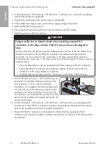
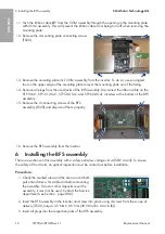
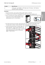
4. Push the ribbon cable
X1
through the respective opening in the COM assembly mounting
plate. This will prevent the cable being pinched during mounting.
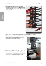
5. Insert the mounting plate of the COM assembly into the inverter. Put the mounting plate onto
the inverter enclosure spacers. Ensure that the spacers match the respective holes in the
mounting plate and that the cables are not trapped beneath the mounting plate.
6. Tighten the 4 mounting plate connecting screws (TX20, torque: 3.5 Nm ± 0.5 Nm (30.98 in-lb
± 4.43 in-lb)).
7. Insert all plugs into the respective jacks of the mounting plate of the COM assembly.
8. Set the ferrite around the ribbon cable
X1
. When doing so, ensure that the cable is not
trapped and damaged.
7
Commissioning the Inverter
Requirements:
☐ The AC circuit breaker must be correctly rated and mounted.
☐ The inverter must be correctly mounted.
☐ All cables must be correctly connected.
☐ Unused enclosure openings must be sealed tightly with sealing plugs.
Procedure:
1. Carry out the necessary tests according to the locally applicable laws, standards and
directives for the correct recommissioning after power assembly replacement. Take the
requirements for component replacements into account (see Section 2.2, page 8).
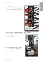
2. Ensure that the grounding conductor in the inverter is correctly connected and functions
properly.
3. Ensure that the DC load-break switch is turned to position
0
.
4. For STP 50-US-40 / STP 33-US-41 / STP 50-US-41 / STP 62-US-41: Ensure that the AC load-
break switch is turned to position
0
.
5. To avoid invalid serial numbers from being sent to the data logger, commission the inverter
without being connected to the local network first. To do this, ensure that the RJ45 connection
to the network is not established.
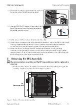
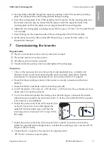
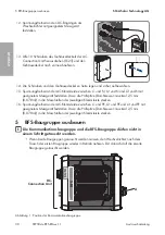
6. Position the enclosure lid of the AC-Connection Unit
on the AC-Connection Unit and first tighten the
upper-left and lower-right screws, and then the
remaining screws crosswise (TX 25, torque: 6 Nm
(53 in-lb)).
2
1
10x
10x
7. Position the enclosure lid of the DC-Connection Unit on the DC-Connection Unit and first
tighten the upper-left and lower-right screws, and then the remaining screws crosswise (TX 25,
torque: 6 Nm (53 in-lb)).
8. Connect the DC connector to the inverter in its original position.
☑ The DC connectors snap into place.
ENGLISH
Summary of Contents for STP 33-US-41
Page 57: ...1 SMA Solar Technology AG STP50 4x BFS RM xx 11 57 1 5 1 6 X703 1 X703 6 10...
Page 60: ...2 SMA Solar Technology AG STP50 4x BFS RM xx 11 60 DC DC DC DC 5...
Page 61: ...2 SMA Solar Technology AG STP50 4x BFS RM xx 11 61 AC DC DC AC DC 1000 V...
Page 62: ...2 SMA Solar Technology AG STP50 4x BFS RM xx 11 62 DC 5 C v v...
Page 67: ...5 BFS SMA Solar Technology AG STP50 4x BFS RM xx 11 67 5 DC DC DC 1 1 6 DC DC DC 7 8 X1...
Page 196: ...1 SMA Solar Technology AG STP50 4x BFS RM xx 11 196 1 5 1 6 X703 1 X703 6 10 WCtlHz Hz...
Page 198: ...2 SMA Solar Technology AG STP50 4x BFS RM xx 11 198 2 2 5 DC DC DC DC DC...
Page 199: ...2 SMA Solar Technology AG STP50 4x BFS RM xx 11 199 5 AC DC DC AC...
Page 200: ...2 SMA Solar Technology AG STP50 4x BFS RM xx 11 200 DC 1000 V DC 5 C...
Page 205: ...5 BFS SMA Solar Technology AG STP50 4x BFS RM xx 11 205 5 DC DC DC 1 1 6 DC DC DC 1 7 8 X1...
Page 211: ......
Page 212: ...www SMA Solar com...

