background image

1 Υποδείξεις για αυτό το έγγραφο

SMA Solar Technology AG

Οδηγίες αντικατάστασης

STP50-4x-BFS-RM-xx-11

56

1

Υποδείξεις για αυτό το έγγραφο

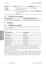
1.1

Τομέας ισχύος

Αυτό το έγγραφο ισχύει για:

• NR-PL-BFS5-xx (συγκρότημα BFS για STP 50-40)
• NR-PL-BFS50-41-x (συγκρότημα BFS για STP 50-41)
• NR-PL-BFS5-US-xx (συγκρότημα BFS για STP 50-US-40)
• NR-PL-BFS33-US41-x (συγκρότημα BFS για STP 33-US-41)
• NR-PL-BFS50-US41-x (συγκρότημα BFS για STP 50-US-41)
• NR-PL-BFS62-US41-x (συγκρότημα BFS για STP 62-US-41)
• NR-PL-BFS5-JP-xx (συγκρότημα BFS για STP 50-JP-40)

1.2

Σε ποιους απευθύνεται

Οι εργασίες που περιγράφονται στο παρόν έγγραφο, επιτρέπεται να εκτελούνται αποκλειστικά από
ειδικευμένο προσωπικό. Το ειδικευμένο προσωπικό πρέπει να διαθέτει τα ακόλουθα προσόντα:

• Εντός της εγγύησης κατασκευαστή SMA είναι υποχρεωτική η συμμετοχή σε ένα σεμινάριο

εκπαίδευσης της SMA για τη διενέργεια των εργασιών που περιγράφονται στο παρόν
έγγραφο. Το είδος της εκπαίδευσης και τα μέσα που χρησιμοποιούνται ενδέχεται να
διαφέρουν μεταξύ τους ανάλογα με τη χώρα. Ο τρόπος της εκπαίδευσης ενδέχεται επομένως
να διαφέρει από χώρα σε χώρα, πρέπει όπως να έχει πραγματοποιηθεί πριν από την παροχή
της υπηρεσίας.

• Εκτός της εγγύησης κατασκευαστή SMA, η SMA Solar Technology AG προτείνει τη

συμμετοχή σε ένα σεμινάριο εκπαίδευσης της SMA για τη διενέργεια των εργασιών που
περιγράφονται στο παρόν έγγραφο. Έτσι εξασφαλίζονται οι απαιτήσεις ποιότητας για μια
σωστή αντικατάσταση συγκροτημάτων. Το είδος της εκπαίδευσης και τα μέσα που
χρησιμοποιούνται ενδέχεται να διαφέρουν μεταξύ τους ανάλογα με τη χώρα.

• Ασφαλής εργασία για την απομόνωση μετατροπέων SMA από την τάση
• Γνώση του τρόπου λειτουργίας και της λειτουργίας ενός μετατροπέα
• Εκπαίδευση για την εγκατάσταση και τη θέση σε λειτουργία ηλεκτρικών συσκευών και

εγκαταστάσεων

• Γνώση των σχετικών νόμων, προτύπων και οδηγιών
• Γνώση και τήρηση του παρόντος εγγράφου με όλες τις υποδείξεις ασφαλείας

1.3

Περιεχόμενα και δομή του εγγράφου

Σε αυτό το έγγραφο περιγράφεται η αντικατάσταση στοιχείων.
Οι εικόνες στο παρόν έγγραφο περιορίζονται στις σημαντικότερες λεπτομέρειες και ενδέχεται να
διαφέρουν από το πραγματικό προϊόν.

1.4

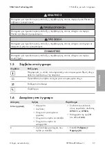
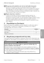
Επίπεδα προειδοποιητικών υποδείξεων

Κατά την εργασία με το προϊόν μπορεί να συναντήσετε τα ακόλουθα επίπεδα προειδοποιητικών
υποδείξεων.

ΕΛΛΗΝΙΚΑ

Summary of Contents for STP 33-US-41

Page 1: ...STP 50 41 CORE1 US STP 50 US 40 STP 33 US 41 STP 50 US 41 STP 62 US 41 CORE1 JP STP 50 JP 40 NR PL BFS5 xx NR PL BFS50 41 x NR PL BFS5 US xx NR PL BFS33 US41 x NR PL BFS50 US41 x NR PL BFS62 US41 x N...

Page 2: ...v m n 37 54 ESPA OL Instrucciones para la sustituci n 72 FRAN AIS Instructions de remplacement 90 ITALIANO Istruzioni per la sostituzione 108 NEDERLANDS Vervangingshandleiding 125 PORTUGU S Manual de...

Page 3: ...indirect incidental or consequential damages under any circumstances The exclusion of implied warranties may not apply in all cases under some statutes and thus the above exclusion may not apply Spec...

Page 4: ...warning messages 5 1 5 Symbols in the Document 6 1 6 Typographical Elements in the Document 6 1 7 Designations in the Document 7 2 Safety 7 2 1 Intended Use 7 2 2 IMPORTANT SAFETY INSTRUCTIONS 8 3 Sco...

Page 5: ...y to country but must have been completed before the service is provided Outside the SMA factory warranty SMA Solar Technology AG recommends participation in an SMA training course to perform the acti...

Page 6: ...hat is important for a specific topic or goal but is not safety rele vant Indicates a requirement for meeting a specific goal Desired result Example 1 6 Typographical Elements in the Document Typograp...

Page 7: ...AG Unauthorized alterations will void guarantee and warranty claims and in most cases terminate the operating license SMA Solar Technology AG shall not be held liable for any damage caused by such cha...

Page 8: ...of the inverter Touching live parts and cables of the inverter results in death or lethal injuries due to electric shock Disconnect the inverter from voltage sources and make sure it cannot be reconne...

Page 9: ...ct actions on the inverter Ensure that unauthorized persons have no access to the inverter Do not operate the AC or DC load break switch on the inverter in case of an error Disconnect the PV array fro...

Page 10: ...conditions If you open the inverter when temperatures are below freezing the enclosure seals can be damaged This can lead to moisture entering the inverter Only open the inverter if the ambient tempe...

Page 11: ...lly visible damage Contact the Service if the delivery is incomplete or damaged Designation Quantity BFS Assembly 1 Bolt M4 x 15 8 Replacement Manual 1 4 Disconnecting the Inverter from Voltage Source...

Page 12: ...ill result in death or serious injury due to electric shock Wear insulated gloves and use insulated tools when working on the DC connectors Ensure that the DC connectors are in perfect condition and t...

Page 13: ...test probe maximum diameter 2 5 mm 0 078 in into the measuring points of the respective terminal blocks 16 Ensure that there is no voltage on the AC terminal block between L1 and grounding conductor L...

Page 14: ...itors are discharged 3 Release TX25 all 10 screws of the enclosure lid of the DC Connection Unit and remove the enclosure lid carefully towards the front 10x 4 Discharge the DC Connection Unit at the...

Page 15: ...blue conductor against grounding conductor 7 Ground yourself prior to replacing the assembly to prevent ESD damage 8 Remove the cable tie from the ferrite of the ribbon cable X1 9 Remove all plugs fr...

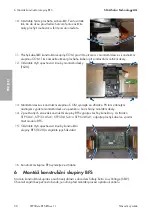
Page 16: ...US 41 inverters at the bottom of the BFS assembly 15 Remove the 4 connecting screws of the BFS assembly TX20 and dispose of them properly 16 Remove the BFS assembly from the inverter 6 Installing the...

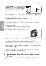
Page 17: ...the necessary tests according to the locally applicable laws standards and directives for the correct recommissioning after power assembly replacement Take the requirements for component replacements...

Page 18: ...hronized with the inverter An inverter update of the inverter can also be carried out 15 If the red LED lights up an event has occurred Find out which event has occurred and if necessary initiate coun...

Page 19: ...zuf llige Folgeverluste oder Sch den Der oben genannte Ausschluss von impliziten Gew hrleistungen kann nicht in allen F llen angewendet werden nderungen an Spezifikationen bleiben vorbehalten Es wurde...

Page 20: ...21 1 4 Warnhinweisstufen 21 1 5 Symbole im Dokument 22 1 6 Auszeichnungen im Dokument 22 1 7 Benennungen im Dokument 23 2 Sicherheit 23 2 1 Bestimmungsgem e Verwendung 23 2 2 Wichtige Sicherheitshinwe...

Page 21: ...chulung kann daher von Land zu Land unterschiedlich sein muss aber vor Leistungserbringung durchlaufen worden sein Au erhalb der SMA Werksgarantie empfiehlt SMA Solar Technology AG die Teilnahme an ei...

Page 22: ...Warnhinweis dessen Nichtbeachtung zu Sachsch den f hren kann 1 5 Symbole im Dokument Symbol Erkl rung Information die f r ein bestimmtes Thema oder Ziel wichtig aber nicht sicher heitsrelevant ist Vor...

Page 23: ...1 NR PL BFS50 US41 x STP 50 US 41 NR PL BFS62 US41 x STP 62 US 41 NR PL BFS5 JP xx STP 50 JP 40 Setzen Sie SMA Produkte ausschlie lich nach den Angaben der beigef gten Dokumentationen und gem der vor...

Page 24: ...hinweise Anleitung aufbewahren Dieses Kapitel beinhaltet Sicherheitshinweise die bei allen Arbeiten immer beachtet werden m ssen Das Produkt wurde gem internationaler Sicherheitsanforderungen entworfe...

Page 25: ...t trennen Bei allen Arbeiten geeignete pers nliche Schutzausr stung tragen GEFAHR Lebensgefahr durch Stromschlag beim Ber hren unter Spannung stehender Anlagenteile bei einem Erdschluss Bei einem Erds...

Page 26: ...Reparaturarbeiten nur mit pers nlicher Schutzausr stung f r den Umgang mit Gefahrstoffen z B Schutzhandschuhe Augen und Gesichtsschutz und Atemschutz durchf hren WARNUNG Verletzungsgefahr durch giftig...

Page 27: ...Wechselrichters durch Sand Staub und Feuchtigkeit Durch das Eindringen von Sand Staub und Feuchtigkeit kann der Wechselrichter besch digt und die Funktion beeintr chtigt werden Den Wechselrichter nur...

Page 28: ...en Dabei immer die vorgegebene Reihenfolge einhalten WARNUNG Lebensgefahr durch Stromschlag bei Zerst rung eines Messger ts durch berspannung Eine berspannung kann ein Messger t besch digen und zum An...

Page 29: ...ertes Werkzeug verwenden Sicherstellen dass die DC Steckverbinder in einem einwandfreien Zustand sind und keine DC Leiter oder DC Steckerkontakte freigelegt sind Die DC Steckverbinder vorsichtig entri...

Page 30: ...Pr fspitze Durchmesser maximal 2 5 mm 0 078 in in die Mess Stellen der jeweiligen Klemmleiste stecken 16 Spannungsfreiheit an der AC Klemmleiste zwischen L1 und PE L2 und PE und L3 und PE mit geeigne...

Page 31: ...Kondensatoren entladen sind 3 Alle 10 Schrauben des Geh usedeckels der DC Connection Unit herausdrehen TX25 und den Geh usedeckel nach vorne abnehmen 10x 4 Die DC Connection Unit mit einem Spannungsp...

Page 32: ...Leiter gegen PE 7 Erden Sie sich vor dem Tausch der Baugruppe um ESD Sch den zu vermeiden 8 Den Kabelbinder am Ferrit des Flachbandkabels X1 entfernen 9 Alle Stecker aus den verwendeten Buchsen der K...

Page 33: ...hen Das Flachbandkabel bei den Wechselrichtern STP 50 41 STP 33 US 41 STP 50 US 41 und STP 62 US 41am unteren Teil der BFS Baugruppe abziehen 15 Die 4 Befestigungsschrauben der BFS Baugruppe entfernen...

Page 34: ...en Der AC Leitungsschutzschalter muss korrekt ausgelegt und installiert sein Der Wechselrichter muss korrekt montiert sein Alle Kabel m ssen korrekt angeschlossen sein Nicht verwendete Geh use ffnunge...

Page 35: ...stellen I 13 Wenn bei der Erstinbetriebnahme die gr ne und die rote LED gleichzeitig blinken ist der Betrieb gestoppt weil noch kein L nderdatensatz eingestellt ist Damit der Wechselrichter den Betri...

Page 36: ...Baugruppe f r den Versand verpacken Dabei die Originalverpackung oder eine Verpackung verwenden die sich f r Gewicht und Gr e der Baugruppe eignet Den R ckversand an SMA Solar Technology AG organisie...

Page 37: ...p m i n hodn n sledn ztr ty nebo kody V e uvedenou v luku implicitn ch z ruk nelze aplikovat ve v ech p padech Vyhrazujeme si pr vo na zm ny specifikac Maxim ln usilujeme o to abychom tento dokument v...

Page 38: ...ozorn n 39 1 5 Symboly v dokumentu 40 1 6 Typografick konvence v dokumentu 40 1 7 Ozna en v tomto dokumentu 41 2 Bezpe nost 41 2 1 Pou it v souladu s ur en m 41 2 2 D le it bezpe nostn upozorn n 42 3...

Page 39: ...m e li it kolen mus ale prob hnout p ed poskytnut m slu by Mimo z ruku v robce SMA doporu uje spole nost SMA Solar Technology AG k prov d n innost popsan ch v tomto dokumentu ast na kolen spole nosti...

Page 40: ...ur it c l d le it ale net k se bez pe nosti Podm nka kter mus b t pro dosa en ur it ho c le spln na douc v sledek P klad 1 6 Typografick konvence v dokumentu Grafick prava Pou it P klad Tu n Hl en P...

Page 41: ...vedou ke ztr t n rok vypl vaj c ch ze z ruky a odpov dnosti za vady a zpravidla tak k z niku povolen k provozu Odpov dnost spole nosti SMA Solar Technology AG za kody zp soben v d sledku takov ch z s...

Page 42: ...ter jsou pod nap t m je p tomn vysok nap t Kontakt s d ly nebo kabely st da e pod nap t m zp sob smrteln raz nebo t k poran n elektrick m proudem P ed prov d n m prac st da odpojte od nap t a zajist t...

Page 43: ...d poruchy neprov d jte na st da i dn p m kony Zajist te aby ke st da i nem ly p stup nepovolan osoby V p pad poruchy nepou vejte AC nebo DC odp na z t e na st da i FV panely odpojte od st da e extern...

Page 44: ...n t sn n krytu p i mrazu Pokud st da otev ete p i mrazu m e se po kodit t sn n krytu Do st da e tak m e vnikat vlhkost kter ho po kod St da otv rejte jen tehdy pokud teplota okol neklesne pod 5 C Je l...

Page 45: ...zda nen zvn j ku viditeln po kozen V p pad nekompletn dod vky nebo po kozen kontaktujte servis Ozna en Po et Modul BFS 1 roub M4 15 8 N vod k v m n 1 4 Odpojen st da e od nap t P ed prov d n m jak chk...

Page 46: ...s DC vodi i nebo kontakty DC konektoru pod nap t m vede k usmrcen nebo k t k m poran n m v d sledku z sahu elektrick m proudem P i prac ch na DC konektorech pou vejte izolovan rukavice a izolovan n ad...

Page 47: ...t K tomu je t eba abyste m ic hrot pr m r max 2 5 mm 0 078 in zastr ili do m ic ch bod p slu n svorkovnice 16 Pomoc vhodn ho m ic ho p stroje na AC svorkovnici zkontrolujte zda mezi L1 a PE L2 a PE a...

Page 48: ...kondenz tory budou vybit 3 Vy roubujte v ech 10 roub v ka krytu jednotky DC Connection Unit TX25 a v ko krytu sejm te sm rem vp ed 10x 4 Jednotku DC Connection Unit vybijte na kontaktn ch bodech pomo...

Page 49: ...na e ka d kontakt DC a DC proti PE erven modr b l ern ed zelen fialov a modr vodi e proti PE 7 P ed v m nou modulu se uzemn te abyste zabr nili kod m zp soben m elektrostatick m v bojem 8 Na feritu p...

Page 50: ...ont n desku s konstruk n skupinou COM vyndejte ze st da e P i tom zahnut m n strojem vypa te mont n desku z upevn n u horn hrany mont n desky 14 Z pou van ch z suvek konstruk n skupiny BFS vypojte v e...

Page 51: ...ont n desky konstruk n skupiny COM zapojte v echny z str ky 8 Kolem ploch ho kabelu X1 polo te ferit Zajist te aby nedo lo ke sk pnut a po kozen kabelu 7 Uveden st da e do provozu Podm nky AC jisti ve...

Page 52: ...e P ibli n po 90 sekund ch v echny t i LED diody op t zhasnou 12 DC odp na z t e st da e nastavte do polohy I I 13 Pokud p i prvn m uveden do provozu soub n blik zelen a erven LED dioda je provoz zast...

Page 53: ...slat zp t zabalte ji pro odesl n Pou ijte k tomu p vodn obal nebo jin obal kter vyhovuje hmotnosti a velikosti konstruk n skupiny Zorganizujte zasl n zp t spole nosti SMA Solar Technology AG Za t mto...

Page 54: ...Solar Technology AG SMA Solar Technology AG SMA Solar Technology AG SMA Solar Technology AG SMA Solar Technology AG SMA Solar Technology AG Sonnenallee 1 34266 Niestetal 49 561 9522 0 49 561 9522 100...

Page 55: ...SMA Solar Technology AG STP50 4x BFS RM xx 11 55 1 56 1 1 56 1 2 56 1 3 56 1 4 56 1 5 57 1 6 57 1 7 58 2 58 2 1 58 2 2 59 3 63 4 63 5 BFS 66 6 BFS 69 7 70 8 71...

Page 56: ...STP 50 40 NR PL BFS50 41 x BFS STP 50 41 NR PL BFS5 US xx BFS STP 50 US 40 NR PL BFS33 US41 x BFS STP 33 US 41 NR PL BFS50 US41 x BFS STP 50 US 41 NR PL BFS62 US41 x BFS STP 62 US 41 NR PL BFS5 JP xx...

Page 57: ...1 SMA Solar Technology AG STP50 4x BFS RM xx 11 57 1 5 1 6 X703 1 X703 6 10...

Page 58: ...FS 2 2 1 BFS SMA SMA NR PL BFS5 xx STP 50 40 NR PL BFS50 41 x STP 50 41 NR PL BFS5 US xx STP 50 US 40 NR PL BFS33 US41 x STP 33 US 41 NR PL BFS50 US41 x STP 50 US 41 NR PL BFS62 US41 x STP 62 US 41 NR...

Page 59: ...2 SMA Solar Technology AG STP50 4x BFS RM xx 11 59 SMA Solar Technology AG SMA Solar Technology AG 2 2 5...

Page 60: ...2 SMA Solar Technology AG STP50 4x BFS RM xx 11 60 DC DC DC DC 5...

Page 61: ...2 SMA Solar Technology AG STP50 4x BFS RM xx 11 61 AC DC DC AC DC 1000 V...

Page 62: ...2 SMA Solar Technology AG STP50 4x BFS RM xx 11 62 DC 5 C v v...

Page 63: ...3 SMA Solar Technology AG STP50 4x BFS RM xx 11 63 SMA SMA SMA Solar Technology AG 3 BFS 1 M4x15 8 1 4 DC 1000 V...

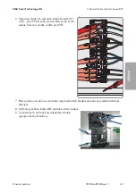
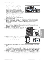
Page 64: ...Technology AG STP50 4x BFS RM xx 11 64 firmware firmware firmware firmware 1 AC 2 STP 50 US 40 STP 33 U S 41 STP 50 US 41 STP 62 US 41 AC O 3 DC O 4 5 LED 6 DC 7 DC 8 DC DC DC DC DC DC DC DC DC DC DC...

Page 65: ...50 41 STP 50 JP 40 DC Sunclix DC 3 5 mm DC DC 1 2 10 STP 50 US 40 STP 33 US 41 STP 50 US 41 STP 62 US 41 DC Amphenol DC 11 DC DC DC DC DC 12 DC A B C 30V 13 10 AC Connection Unit 25 10x 14 15 AC L1 N...

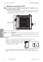
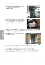
Page 66: ...lar Technology AG STP50 4x BFS RM xx 11 66 5 BFS BFS DC Connection Unit COM LED A BFS 1 A AC STP 50 US 40 STP 33 US 41 STP 50 US 41 STP 62 US 41 1 4 63 2 5 3 10 DC Connection Unit 25 10x 4 DC Connecti...

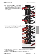
Page 67: ...5 BFS SMA Solar Technology AG STP50 4x BFS RM xx 11 67 5 DC DC DC 1 1 6 DC DC DC 7 8 X1...

Page 68: ...5 BFS SMA Solar Technology AG STP50 4x BFS RM xx 11 68 9 10 X1 11 X1 COM COM 12 4 TX20 13 COM 14 BFS STP 50 41 STP 33 US 41 STP 50 US 41 STP 62 US 41 BFS...

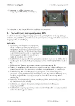
Page 69: ...ogy AG STP50 4x BFS RM xx 11 69 15 4 BFS TX20 16 BFS 6 BFS Safety Extra Low Voltage SELV 1 000 2 BFS 4 TX20 3 5 Nm 0 5 Nm 30 98 in lb 4 43 in lb 3 BFS 4 X1 COM 5 COM 6 4 TX20 3 5 Nm 0 5 Nm 30 98 in lb...

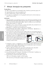
Page 70: ...50 US 40 STP 33 US 41 STP 50 US 41 STP 62 US 41 C 0 5 RJ45 6 C Connection Unit C Connection Unit TX25 6 Nm 53 in lb 2 1 10x 10x 7 DC Connection Unit DC Connection Unit TX25 6 Nm 53 in lb 8 DC DC 9 DC...

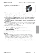
Page 71: ...8 SMA Solar Technology AG STP50 4x BFS RM xx 11 71 12 DC I 13 LED 14 15 15 LED 16 5 SMA 17 8 1 SMA Solar Technology AG 2...

Page 72: ...ltante bajo ninguna circunstancia La exclusi n de garant as impl citas puede no ser aplicable en todos los casos seg n algunos estatutos y por tanto la exclusi n mencionada anteriormente puede no ser...

Page 73: ...de advertencia 74 1 5 S mbolos del documento 75 1 6 Marcas de texto en el documento 75 1 7 Denominaci n en el documento 76 2 Seguridad 76 2 1 Uso previsto 76 2 2 Indicaciones importantes para la segu...

Page 74: ...tes de que se preste el servicio Despu s de expirar la garant a del fabricante SMA Solar Technology AG recomienda la participaci n en una formaci n de SMA para llevar a cabo las tareas descritas en el...

Page 75: ...ortante para un tema u objetivo concretos aunque no rele vante para la seguridad Requisito necesario para alcanzar un objetivo determinado Resultado deseado Ejemplo 1 6 Marcas de texto en el documento...

Page 76: ...Los cambios no autorizados conllevan la p rdida de los derechos de garant a as como la extinci n de la autorizaci n de operaci n Queda excluida la responsabilidad de SMA Solar Technology AG por los da...

Page 77: ...ntes conductores de tensi n o cables del inversor puede causar la muerte o lesiones mortales por descarga el ctrica Antes de cualquier trabajo desconecte el inversor y asegure el producto contra cualq...

Page 78: ...rse en caso de error una mezcla de gas inflamable en el interior del inversor En este estado puede producirse un incendio en el interior del inversor o una explosi n durante las actividades de conmuta...

Page 79: ...e da ar un equipo de medici n y provocar que exista tensi n en la carcasa del equipo de medici n Tocar la carcasa del equipo de medici n bajo tensi n puede causar la muerte o lesiones mortales por des...

Page 80: ...de forma intuitiva aseg rese de que el conductor de protecci n del inversor est conectado correctamente El conductor de protecci n debe funcionar correctamente y deben tenerse en cuenta todas las ley...

Page 81: ...puesta en marcha sin problemas del subgrupo el firmware del inversor debe actualizarse a la versi n actual antes de desconectar el inversor Antes de desconectar compruebe si el firmware del inversor...

Page 82: ...descubierto Desbloquear y extraer los conectadores de enchufe con cuidado tal y como se describe a continuaci n 9 En STP 50 40 STP 50 41 STP 50 JP 40 utilizaci n de conectadores de enchufe de CC de Su...

Page 83: ...equipo de medici n adecuado que no haya tensi n en la caja de bornes de AC entre L1 y PE L2 y PE y L3 y PE Para ello introduzca la punta de comprobaci n di metro m ximo 2 5 mm 0 078 in en el punto de...

Page 84: ...e la tapa de la carcasa tirando de ella hacia delante TX 25 10x 4 Descargue la Connection Unit CC con un detector de tensi n sin una fuente de tensi n propia en los puntos de contacto Aseg rese de que...

Page 85: ...conductor de protecci n los conductores rojos azules blancos negros grises verdes morados y azules contra el conductor de protecci n 7 Para evitar da os por descargas electrost ticas p ngase a tierra...

Page 86: ...taje TX20 13 Retire la placa de montaje del subgrupo COM del inversor Utilice una herramienta angular para sacar la placa de montaje de la fijaci n en el borde superior de la placa de montaje 14 Retir...

Page 87: ...ca de montaje TX20 par de apriete 3 5 Nm 0 5 Nm 30 98 in lb 4 43 in lb 7 Inserte todos los conectores en los conectores hembra correspondientes de la placa de montaje del subgrupo COM 8 Coloque la fer...

Page 88: ...1 STP 62 US 41 coloque el interruptor seccionador de CA del inversor en la posici n I 11 Conecte el disyuntor de CA Los tres leds se iluminan Comienza la fase de arranque Los tres leds se apagan de nu...

Page 89: ...el subgrupo averiado Procedimiento 1 Si el subgrupo defectuoso debe devolverse emb lelo para el env o Utilice para ello el embalaje original o bien otro que sea adecuado para el peso y tama o del sub...

Page 90: ...pectifs ne sauraient et ce sous aucune circonstance tre tenus responsables en cas de pertes ou de dommages directs indirects ou accidentels L exclusion susmentionn e des garanties implicites peut ne p...

Page 91: ...n garde 92 1 5 Symboles utilis s dans le document 93 1 6 Formats utilis s dans le document 93 1 7 D signations utilis es dans le document 94 2 S curit 94 2 1 Utilisation conforme 94 2 2 Consignes de s...

Page 92: ...ectu e avant que la prestation ne soit fournie En dehors de la garantie constructeur SMA SMA Solar Technology AG recommande de participer une formation SMA pour ex cuter les op rations d crites dans c...

Page 93: ...ur un th me ou un objectif pr cis mais ne relevant pas de la s curit Condition qui doit tre remplie pour atteindre un objectif pr cis R sultat souhait Exemple 1 6 Formats utilis s dans le document For...

Page 94: ...riels Les interventions sur les produits SMA modifications ou transformations par exemple ne sont autoris es qu apr s accord crit expr s de SMA Solar Technology AG Toute intervention non autoris e ent...

Page 95: ...durable du produit DANGER Danger de mort par choc lectrique en cas de contact avec des composants conducteurs ou des c bles de l onduleur Les composants conducteurs ou les c bles de l onduleur sont s...

Page 96: ...ent tre g n r s dans l onduleur en cas de dysfonctionnement Les op rations de commutation risquent dans ce cas de provoquer un incendie ou une explosion dans l onduleur Il peut en r sulter la mort ou...

Page 97: ...nsion peut endommager un appareil de mesure et cr er une tension au niveau du bo tier de l appareil de mesure Le contact avec le bo tier sous tension de l appareil de mesure entra ne des blessures gra...

Page 98: ...la remise en service d onduleurs SMA survenant apr s l installation de composants ou de modules de puissance SMA ne se rempla ant pas de mani re intuitive assurez vous que le conducteur de protection...

Page 99: ...00 V ou sup rieure Mise jour du firmware avant la mise hors tension de l onduleur Afin de garantir une mise en service sans probl me de l ensemble le micrologiciel de l onduleur doit tre mis jour la v...

Page 100: ...ez les connecteurs DC avec pr caution comme d crit ci apr s 9 Pour les STP 50 40 STP 50 41 STP 50 JP 40 utilisation de connecteurs DC SUNCLIX d verrouillez et retirez les connecteurs DC Ins rez un tou...

Page 101: ...re adapt v rifiez que les plaques bornes AC entre L1 et le conducteur de protection L2 et le conducteur de protection et L3 et le conducteur de protection sont bien hors tension Pour ce faire ins rez...

Page 102: ...de la Connection Unit DC TX 25 et retirez le couvercle du bo tier en le tirant vers l avant 10x 4 D chargez la Connection Unit DC sur les points de contact avec le d tecteur de tension sans sa propre...

Page 103: ...ur de protection le conducteur rouge bleu blanc noir gris vert violet et bleu contre le conducteur de protection 7 Reliez vous la terre avant le remplacement du module de construction pour viter des d...

Page 104: ...e la plaque de montage TX20 13 Retirez de l onduleur la plaque de montage avec l ensemble COM l aide d un outil coud faites levier sur le bord sup rieur de la plaque de montage pour la sortir de sa fi...

Page 105: ...e la plaque de montage TX20 couple de serrage 3 5 Nm 0 5 Nm 30 98 in lb 4 43 in lb 7 Ins rez toutes les fiches dans les embases correspondantes sur la plaque de montage de l ensemble COM 8 Placez la f...

Page 106: ...50 US 41 STP 62 US 41 r glez l interrupteur sectionneur AC de l onduleur sur la position I 11 Activez le disjoncteur miniature AC Les 3 DEL s allument La phase de d marrage commence Au bout de 90 seco...

Page 107: ...ommande Proc dure 1 Si l ensemble d fectueux doit tre renvoy emballez l ensemble d fectueux pour l exp dition Utilisez pour ce faire l emballage d origine ou un emballage appropri au poids et la taill...

Page 108: ...eguenti o danni diretti o indiretti La suddetta esclusione di garanzie di legge implicite non si applica in altri casi Con riserva di modifiche delle specifiche stato fatto il possibile per redigere q...

Page 109: ...rtenze di sicurezza 110 1 5 Simboli nel documento 111 1 6 Convenzioni tipografiche nel documento 111 1 7 Denominazioni nel documento 112 2 Sicurezza 112 2 1 Utilizzo conforme 112 2 2 Avvertenze di sic...

Page 110: ...i variare da paese a paese ma deve comunque essere stata svolta prima di prestare il servizio Al di fuori della garanzia del produttore SMA Solar Technology AG raccomanda di partecipare all offerta fo...

Page 111: ...documento Simbolo Spiegazione Informazioni importanti per un determinato obiettivo o argomento non rilevan ti tuttavia dal punto di vista della sicurezza Condizioni preliminari necessarie per un dete...

Page 112: ...G Eventuali interventi non autorizzati comportano l estinzione dei diritti di garanzia e di regola come anche la revoca dell autorizzazione di funzionamento esclusa ogni responsabilit di SMA Solar Tec...

Page 113: ...esenti tensioni elevate Il contatto con componenti sotto tensione o cavi dell inverter pu determinare la morte o lesioni mortali per folgorazione Prima di qualsiasi intervento togliere tensione all in...

Page 114: ...n rari casi in presenza di un guasto pu crearsi una miscela di gas infiammabile all interno dell inverter In caso di attivazione tale situazione all interno dell inverter pu provocare un incendio o un...

Page 115: ...causare la presenza di tensione sull involucro dell apparecchio di misurazione Il contatto con l involucro sotto tensione dell apparecchio di misurazione causa la morte o lesioni mortali per folgoraz...

Page 116: ...uitiva accertarsi che il conduttore di protezione sia collegato correttamente nell inverter Il funzionamento del conduttore di protezione deve essere garantito e devono essere rispettate le norme e le...

Page 117: ...rimento involontario 2 Per STP 50 US 40 STP 33 US 41 STP 50 US 41 STP 62 US 41 portare il sezionatore di carico CA dell inverter in posizione O 3 Portare il sezionatore di carico CC dell inverter in p...

Page 118: ...12 Accertare l assenza di tensione sugli ingressi CC dell inverter mediante un apposito apparecchio di misurazione A B C 30V 13 Svitare tutte e 10 le viti del coperchio dell involucro della AC Connec...

Page 119: ...US 41 e STP 62 US 41 Procedura 1 Disinserire l inverter v cap 4 pag 116 2 Attendere 5 minuti In questo modo si certi che i condensatori si siano scaricati 3 Svitare tutte e 10 le viti del coperchio de...

Page 120: ...e bianco verso 1 conduttore nero nonch il conduttore grigio verde e lilla verso 1 conduttore blu 6 Sulla destra dell interruttore CC scaricare ogni contatto CC e CC verso PE il conduttori rosso blu b...

Page 121: ...l apertura della piastra di montaggio con il gruppo COM In questo modo si evita che il cavo piatto si strappi durante la rimozione della la piastra di montaggio 12 Rimuovere le 4 viti di fissaggio de...

Page 122: ...n lb 3 Inserire tutti i connettori nelle corrispondenti prese del gruppo BFS 4 Spingere il cavo piatto X1 attraverso l apertura corrispondente della piastra di montaggio del gruppo COM In questo modo...

Page 123: ...a stessa e serrare dapprima le vite in alto a sinistra e in basso a destra e poi le altre viti con un cacciavite Torx TX 25 coppia 6 Nm 53 in lb 2 1 10x 10x 7 Posizionare il coperchio dell involucro d...

Page 124: ...o 5 minuti di immissione Se viene visualizzato un numero di serie diverso contattare il Servizio di assistenza tecnica SMA 17 Accertarsi che l inverter immetta senza anomalie 8 Spedizione e smaltiment...

Page 125: ...bovengenoemde uitsluiting van impliciete garanties kan niet in alle gevallen worden toegepast Wijzigingen van specificaties blijven voorbehouden Dit document is met veel inspanning en uiterst zorgvul...

Page 126: ...s veiligheidswaarschuwing 127 1 5 Symbolen in het document 128 1 6 Markeringen in document 128 1 7 Benamingen in het document 129 2 Veiligheid 129 2 1 Reglementair gebruik 129 2 2 Belangrijke veilighe...

Page 127: ...n de werkzaamheden zijn doorlopen Behalve de SMA fabrieksgarantie adviseert SMA Solar Technology AG is de deelname aan een SMA scholing voor het uitvoeren van de in dit document beschreven werkzaamhed...

Page 128: ...matie die voor een specifiek onderwerp of doel van belang is maar niet relevant is voor de veiligheid Voorwaarde waaraan voor een specifiek doel moet worden voldaan Gewenst resultaat Voorbeeld 1 6 Mar...

Page 129: ...oerd vervalt de garantie en in de meeste gevallen ook de typegoedkeuring SMA Solar Technology AG is in geen geval aansprakelijk voor schade die door zulke wijzigingen is ontstaan Elke vorm van gebruik...

Page 130: ...en Het aanraken van spanningvoerende onderdelen en kabels van de omvormer leidt tot de dood of tot levensgevaarlijk letsel als gevolg van een elektrische schok Schakel de omvormer spanningsvrij en bev...

Page 131: ...g intern in de omvormer een ontvlambaar gasmengsel ontstaan Door schakelhandelingen kan in deze toestand intern in de omvormer een brand of explosie optreden Dodelijk of levensgevaarlijk letsel door h...

Page 132: ...eettoestel beschadigen en elektrische spanning op de behuizing van het meettoestel veroorzaken Het aanraken van een onder spanning staande behuizing van het meettoestel leidt tot de dood of tot levens...

Page 133: ...of vermogensmodules waarborgen dat de aardleiding in de omvormer correct is aangesloten De functie van de aardleiding moet zijn gegeven en alle plaatselijk geldende wetgeving normen en richtlijnen mo...

Page 134: ...Om de inbedrijfstelling van de module probleemloos te laten verlopen moet voor het vrijschakelen van de omvormer een update van de firmware van de omvormer naar de actuele versie worden uitgevoerd Voo...

Page 135: ...connectoren voorzichtig en trek deze los zoals hierna is beschreven 9 Bij STP 50 40 STP 50 41 STP 50 JP 40 gebruik van Sunclix DC connectoren de DC connectoren ontgrendelen en uittrekken Steek hiervoo...

Page 136: ...Verzeker u er met een daartoe geschikt meettoestel van dat er op de AC klemmenstrook geen spanning staat tussen L1 en aardleiding L2 en aardleiding en L3 en aardleiding Steek de sonde daarvoor diamet...

Page 137: ...van de DC Connection Unit uitdraaien TX25 en het behuizingsdeksel naar voren wegnemen 10x 4 De DC Connection Unit met een spanningstester zonder eigen spanningsbron op de contactpunten ontladen Daarbi...

Page 138: ...t DC en DC tegen PE de rode blauwe witte zwarte grijze groene paarse en blauwe geleider tegen PE 7 Aard uzelf voor het vervangen van de module om schade door elektrostatische ontlading te voorkomen 8...

Page 139: ...13 De montageplaat met COM module uit de omvormer wegnemen Daarbij met een haaks gereedschap de montageplaat uit de fixering aan de bovenste rand van de montageplaat tillen 14 Alle stekkers uit de geb...

Page 140: ...Alle stekkers in de overeenkomstige bussen van de montageplaat van de COM module steken 8 De ferriet om de bandkabel X1 plaatsen Daarbij waarborgen dat de kabel niet wordt ingeklemd en beschadigd 7 D...

Page 141: ...artfase begint Na circa 90 seconden gaan alle 3 leds weer uit 12 Stel de DC lastscheider van de omvormer in op de stand I I 13 Wanneer bij de inbedrijfstelling de groene en de rode led tegelijkertijd...

Page 142: ...verpakken Daarbij de originele verpakking gebruiken of een verpakking die geschikt is voor het gewicht en de afmetingen van de module Het retourzenden aan SMA Solar Technology AG organiseren Daarvoor...

Page 143: ...retos ou indiretos A exclus o supracitada das garantias impl citas n o pode ser aplicada a todos os casos Reserva se o direito a altera es s especifica es Foram envidados todos os esfor os para redigi...

Page 144: ...4 N veis de aviso 145 1 5 S mbolos no documento 146 1 6 Sinaliza es no documento 146 1 7 Designa es no documento 147 2 Seguran a 147 2 1 Utiliza o prevista 147 2 2 Avisos de seguran a importantes 148...

Page 145: ...s para pa s mas deve ter sido conclu do antes de o servi o ser prestado Fora do mbito da garantia do fabricante SMA a SMA Solar Technology AG recomenda a participa o numa a o de forma o SMA para pode...

Page 146: ...ser rele vante para a seguran a Pr requisito que necess rio estar cumprido para se alcan ar um determina do objetivo Resultado pretendido Exemplo 1 6 Sinaliza es no documento Sinaliza o Aplica o Exemp...

Page 147: ...pode resultar em danos f sicos ou materiais Interven es nos produtos SMA p ex modifica es e convers es s s o permitidas se tal for expressamente autorizado por escrito pela SMA Solar Technology AG In...

Page 148: ...s de seguran a PERIGO Perigo de morte devido a choque el trico por contacto com pe as ou cabos condutores de tens o do inversor As pe as ou cabos do inversor condutores de tens o possuem tens es eleva...

Page 149: ...o Em raros casos isolados uma falha pode dar origem forma o de uma mistura de gases inflam vel no interior do inversor Manobras de comuta o nestas circunst ncias podem causar um inc ndio no interior d...

Page 150: ...pode danificar um aparelho de medi o e originar tens o na caixa do aparelho de medi o O contacto com a caixa do aparelho de medi o sob tens o causa de morte ou ferimentos graves devido a choque el tri...

Page 151: ...de pot ncia cuja substitui o n o seja intuitiva assegurar que o condutor de prote o est corretamente ligado no inversor O condutor de prote o deve estar funcional e todas as leis normas e diretivas v...

Page 152: ...inversor para a posi o O 3 Regular o interruptor seccionador de CC do inversor para a posi o O 4 Se o rel multifun es for utilizado desligar a tens o de alimenta o do equipamento consumidor caso neces...

Page 153: ...ctores de ficha CC que est o no produto e os conectores de ficha CC que est o equipados com condutores CC se encontram num estado irrepreens vel e que n o existem condutores CC ou contactos de ficha C...

Page 154: ...dulo de comunica o Posi o Designa o A Interruptor CA dispon vel exclusivamente em STP 50 US 40 STP 33 US 41 STP 50 US 41 e STP 62 US 41 Procedimento 1 Seccionar completamente o inversor ver cap tulo 4...

Page 155: ...l e branco a 1 condutor preto bem como o condutor cinzento verde e lil s a 1 condutor azul 6 No lado direito do interruptor CC cada contacto CC e CC a PE os condutores vermelho azul branco preto cinze...

Page 156: ...trav s da abertura da placa de montagem com o m dulo COM Deste modo ao remover a placa de montagem estar a evitar que o cabo plano seja solto com viol ncia 12 Remover os 4 parafusos de fixa o da placa...

Page 157: ...fornecido TX20 bin rio 3 5 Nm 0 5 Nm 30 98 in lb 4 43 in lb 3 Encaixar todas as fichas das tomadas correspondentes do m dulo BFS 4 Deslizar o cabo plano X1 atrav s da abertura correspondente na placa...

Page 158: ...inversor em funcionamento primeiro sem estar ligado rede local Para isso certificar se de que a liga o RJ45 rede n o foi estabelecida 6 Colocar a tampa da caixa da Connection Unit CA na Connection Un...

Page 159: ...tome as medidas que forem necess rias 16 Verificar se ao fim de 5 minutos no modo de inje o na rede o n mero de s rie da placa de identifica o do inversor exibido na interface de utilizador Se for ex...

Page 160: ...uderea mai sus men ionat a garan iilor implicite nu poate fi aplicat n toate cazurile Ne rezerv m dreptul asupra modific rilor specifica iilor Au fost ntreprinse toate eforturile pentru a ntocmi acest...

Page 161: ...de avertismente 162 1 5 Simbolurile din document 163 1 6 Marcaje n document 163 1 7 Denumirile din document 164 2 Siguran a 164 2 1 Utilizare conform 164 2 2 Indica ii importante de siguran 165 3 Set...

Page 162: ...cursului poate fi diferit de la ar la ar trebuie ns neap rat parcurs nainte de prestarea serviciilor n afara garan iei produc torului SMA SMA Solar Technology AG recomand participarea la un curs organ...

Page 163: ...pentru un anumit scop dar irelevant pentru siguran Condi ie care trebuie ndeplinit pentru atingerea unui anumit scop Rezultat dorit Exemplu 1 6 Marcaje n document Marcaj Utilizare Exemplu bold Mesaje...

Page 164: ...ovoca v t m ri corporale i daune materiale Interven iile n produsele SMA cum sunt modific rile i transform rile sunt permise numai cu acordul expres dat n scris al SMA Solar Technology AG Interven iil...

Page 165: ...toate indica iile de siguran PERICOL Pericol de deces prin electrocutare la atingerea pieselor aflate sub tensiune sau a cablurilor invertorului Componentele purt toare de tensiune sau cablurile inve...

Page 166: ...izolate atunci c nd exist o defec iune se poate forma un amestec de gaze inflamabil n interiorul invertorului Prin comut ri n aceast stare n interiorul invertorului se poate declan a un incendiu sau o...

Page 167: ...uza supratensiunii Supratensiunea poate Atingerea carcasei aflate sub tensiune a aparatului de m sur duce la deces sau la accident ri cu pericol de deces prin electrocutare Nu utiliza i dec t aparate...

Page 168: ...nu pot fi nlocuite intuitiv asigura i v c n invertor este conectat corect conductorul de protec ie Conductorul de protec ie trebuie s fie func ional iar toate legile normele i directivele valabile la...

Page 169: ...62 US 41 Aduce i comutatorul de ntrerupere a sarcinii AC de la invertor n pozi ia O 3 Aduce i comutatorul de ntrerupere a sarcinii DC de la invertor n pozi ia O 4 Dac se utilizeaz releul multifunc io...

Page 170: ...DC care sunt echipa i cu conductori DC sunt ntr o stare irepro abil i c nu exist conductori DC sau contacte de fi DC dezvelite 12 Cu ajutorul unui aparat de m surare adecvat verifica i ca intr rile D...

Page 171: ...zi ia ansamblului de comunica ie Pozi ie Denumire A Comutator AC disponibil exclusiv la STP 50 US 40 STP 33 US 41 STP 50 US 41 i STP 62 US 41 Cum se procedeaz 1 Scoate i invertorul de sub tensiune vez...

Page 172: ...albastru i alb la 1 conductor negru precum i conductorul maro verde i lila la 1 conductor albastru 6 Pe partea dreapt a comutatorului DC fiecare contact DC i DC la PE conductorii ro u albastru alb ne...

Page 173: ...rea pl cii de montaj mpreun cu ansamblul COM n acest fel se mpiedic o eventual rupere a cablului plat la scoaterea pl cii de montaj 12 Scoate i cele 4 uruburi de fixare ale pl cii de montaj TX20 13 Sc...

Page 174: ...m 30 98 in lb 4 43 in lb 3 Introduce i toate fi ele n mufele corespunz toare ale ansamblului BFS 4 Introduce i cablul plat X1 prin deschiderea corespunz toare din placa de montaj a ansamblului COM n a...

Page 175: ...itatea AC Connection Unit str nge i mai nt i urubul din st nga sus i din dreapta jos i apoi celelalte uruburi n cruce TX25 cuplu de str ngere 6 Nm 53 in lb 2 1 10x 10x 7 Pune i capacul carcasei unit i...

Page 176: ...e pe pl cu a de identificare a invertorului Dac se afi eaz un alt num r de serie adresa i v SMA Service 17 Asigura i v c invertorul alimenteaz f r probleme 8 Returnarea sau eliminarea ca de eu a modul...

Page 177: ...gibi do rudan veya dolayl ve tesad fi kay plar ve zararlar i in kesinlikle sorumluluk kabul etmemektedir Yukar da belirtilen z mni garanti istisnas da her durumda uygulanamaz zel ko ullarda de i ikli...

Page 178: ...leri 179 1 5 Dok mandaki semboller 180 1 6 Dok mandaki bi imler 180 1 7 Dok mandaki adland rmalar 181 2 G venlik 181 2 1 Amac na uygun kullan m 181 2 2 nemli g venlik uyar lar 182 3 Teslimat kapsam 18...

Page 179: ...yapmadan nce e itimin ba ar yla tamamlanm olmas zorunludur SMA Solar Technology AG firmas SMA retici garantisi kapsam d nda bu dok manda anlat lan faaliyetlerin uygulanmas i in SMA e itimlerine kat l...

Page 180: ...klama Belirli bir konu veya hedef i in nemli olan ancak g venlikle ilgili olmayan bilgi Belirli bir hedef i in yerine getirilmi olmas gereken ko ul stenen sonu rnek 1 6 Dok mandaki bi imler Bi im Kull...

Page 181: ...aleler garanti ve tazmin taleplerinin ortadan kalkmas na ve ayr ca kural olarak i letim izninin iptaline yol a ar Bu t r m dahalelerden kaynaklanan hasarlarda SMA Solar Technology AG nin hi bir y k ml...

Page 182: ...ar alara veya kablolara dokunuldu unda elektrik arpmas sonucu l m veya l mc l yaralanmalar meydana gelir al malara ba lamadan nce eviriciyi gerilim kaynaklar ndan ay r n ve r n n tekrar al t r lmas n...

Page 183: ...l mc l yaralanmalar meydana gelebilir Hata durumunda eviricinin kendisinde i lem yapmay n Eviriciye yetkisi olmayan ki ilerin eri emeyece inden emin olun Bir hata durumunda evirici zerindeki AC veya...

Page 184: ...u umu Eviriciyi don s ras nda a man z durumunda g vde contas hasar g rebilir Bu durumda eviricinin i ine nem girebilir ve evirici zarar g rebilir Eviriciyi yaln zca ortam s cakl 5 C alt na d memi se a...

Page 185: ...ntrol edin Teslimat kapsam tam olmad nda veya hasar olmas durumunda yetkili servisle ileti ime ge in Tan m Adet BFS tertibat 1 C vata M4x15 8 De i tirme k lavuzu 1 4 Eviricinin gerilim kaynaklar ndan...

Page 186: ...lim ta yan DC iletkenlerine veya DC fi kontaklar na dokunulmas elektrik arpmas sonucu l m veya a r yaralanmalara yol a ar DC fi ba lant lar ndaki al malarda yal t ml eldiven giyin ve yal t ml aletler...

Page 187: ...a gerilim bulunmad ndan emin olun Bunu yapmak i in l m ucunu ap maksimum 2 5 mm 0 078 in ba lant terminali l m yerlerine sokun 16 Uygun bir l m cihaz n kullanarak AC ba lant terminalinde s rayla L1 il...

Page 188: ...erin bo almas sa lan r 3 Do ru Ak m Connection Unit g vde kapa n n 10 c vatas n TX25 kar n ve g vde kapa n ne do ru yerinden kar n 10x 4 Do ru Ak m Connection Unit teki gerilimi kendine ait gerilim ka...

Page 189: ...PE ye do ru 7 Elektrostatik de arj hasarlar n nlemek i in tertibat de i tirmeden kendinizi topraklay n 8 Yass bant kablonun X1 ferrit halkas ndaki kablo ba n kar n 9 T m soketleri ileti im tertibat n...

Page 190: ...bloyu BFS tertibat n n alt par as ndan ay r n 15 BFS tertibat n n 4 sabitleme c vatas n kar n TX20 ve imha edin 16 BFS tertibat n eviriciden kar n 6 BFS tertibat n n monte edilmesi Bu tertibatta emniy...

Page 191: ...an m yerinde ge erli t m yasalar standartlar ve y netmeliklere g re gerekli kontrolleri ger ekle tirin Kontrolde bile en de i ikli i i in ko ullar dikkate al n bkz B l m 2 2 Sayfa 182 2 Eviricide topr...

Page 192: ...nebilir 15 K rm z LED yand takdirde bir olay mevcuttur Hangi durumun s z konusu oldu unu bulun ve gerekirse nlemler al n 16 5 dakikal k gerilim besleme i letiminden sonra eviricinin tip etiketinde yaz...

Page 193: ...nology AG SMA Solar Technology AG SMA Solar Technology AG SMA Solar Technology AG SMA Solar Technology AG SMA Solar Technology AG Sonnenallee 1 34266 Niestetal 49 561 9522 0 FAX 49 561 9522 100 www SM...

Page 194: ...SMA Solar Technology AG STP50 4x BFS RM xx 11 194 1 195 1 1 195 1 2 195 1 3 195 1 4 195 1 5 196 1 6 196 1 7 197 2 197 2 1 197 2 2 198 3 201 4 201 5 BFS 204 6 BFS 207 7 208 8 209...

Page 195: ...P 50 40 BFS NR PL BFS50 41 x STP 50 41 BFS NR PL BFS5 US xx STP 50 US 40 BFS NR PL BFS33 US41 x STP 33 US 41 BFS NR PL BFS50 US41 x STP 50 US 41 BFS NR PL BFS62 US41 x STP 62 US 41 BFS NR PL BFS5 JP x...

Page 196: ...1 SMA Solar Technology AG STP50 4x BFS RM xx 11 196 1 5 1 6 X703 1 X703 6 10 WCtlHz Hz...

Page 197: ...x STP 50 40 NR PL BFS50 41 x STP 50 41 NR PL BFS5 US xx STP 50 US 40 NR PL BFS33 US41 x STP 33 US 41 NR PL BFS50 US41 x STP 50 US 41 NR PL BFS62 US41 x STP 62 US 41 NR PL BFS5 JP xx STP 50 JP 40 SMA S...

Page 198: ...2 SMA Solar Technology AG STP50 4x BFS RM xx 11 198 2 2 5 DC DC DC DC DC...

Page 199: ...2 SMA Solar Technology AG STP50 4x BFS RM xx 11 199 5 AC DC DC AC...

Page 200: ...2 SMA Solar Technology AG STP50 4x BFS RM xx 11 200 DC 1000 V DC 5 C...

Page 201: ...3 SMA Solar Technology AG STP50 4x BFS RM xx 11 201 SMA SMA SMA Solar Technology AG 3 BFS 1 M4 x 15 8 1 4...

Page 202: ...4 SMA Solar Technology AG STP50 4x BFS RM xx 11 202 DC 1000 V 1 AC 2 STP 50 US 40 STP 33 US 41 STP 50 US 41 STP 62 US 41 AC O 3 DC O 4 5 LED 6 DC 7 DC 8 DC DC DC DC DC DC DC DC DC...

Page 203: ...STP 50 40 STP 50 41 STP 50 JP 40 Sunclix DC DC 3 5 mm DC DC 1 2 10 STP 50 US 40 STP 33 US 41 STP 50 US 41 STP 62 US 41 Amphenol DC DC 11 DC DC DC DC 12 DC A B C 30V 13 AC TX25 10 10x 14 15 AC L1 N L2...

Page 204: ...MA Solar Technology AG STP50 4x BFS RM xx 11 204 5 BFS BFS 2 DC Connection Unit COM LED A BFS 1 A AC STP 50 US 40 STP 33 US 41 STP 50 US 41 STP 62 US 41 1 201 4 2 5 3 DC 10 TX25 10x 4 DC Connection Un...

Page 205: ...5 BFS SMA Solar Technology AG STP50 4x BFS RM xx 11 205 5 DC DC DC 1 1 6 DC DC DC 1 7 8 X1...

Page 206: ...5 BFS SMA Solar Technology AG STP50 4x BFS RM xx 11 206 9 10 X1 2 11 COM COM X1 12 TX20 4 13 COM 14 BFS BFS STP 50 41 STP 33 US 41 STP 50 US 41 STP 62 US 41...

Page 207: ...ar Technology AG STP50 4x BFS RM xx 11 207 15 BFS TX20 4 16 BFS 6 BFS SELV 1 210 2 BFS 4 TX20 3 5 Nm 0 5 Nm 30 98 in lb 4 43 in lb 3 BFS 4 COM COM X1 5 COM 6 4 TX20 3 5 Nm 0 5 Nm 30 98 in lb 4 43 in l...

Page 208: ...1 198 2 2 2 3 DC O 4 STP 50 US 40 STP 33 US 41 STP 50 US 41 STP 62 US 41 AC 0 5 RJ45 6 AC AC Torx TX25 6 Nm 53 in lb 2 1 10x 10x 7 DC DC Torx TX25 6 Nm 53 in lb 8 DC DC 9 DC 10 STP 50 US 40 STP 33 US...

Page 209: ...8 SMA Solar Technology AG STP50 4x BFS RM xx 11 209 12 DC I I 13 LED 14 15 15 LED 16 5 SMA 17 8 1 SMA Solar Technology AG 2...

Page 210: ...STP50 4x BFS RM xx 11 210 Contact en Contact de Kontakt cs Kontakt el es Contacto fr Contact it Contatto nl Contact pt Contactos ro Contact tr leti im ja https go sma de service...

Page 211: ......

Page 212: ...www SMA Solar com...

Reviews: