6 Electrical Connection
SMA Solar Technology AG
Operating manual
STP3-6-3AV-40-BE-en-13
30
Grounding conductor monitoring:
The inverter is equipped with a grounding conductor monitoring device. This grounding conductor
monitoring device detects when there is no grounding conductor connected and disconnects the
inverter from the utility grid if this is the case. Depending on the installation site and grid
configuration, it may be advisable to disable the grounding conductor monitoring. This can be
necessary, for example, in a Delta IT system or other grid configurations if there is no neutral
conductor present and you intend to install the inverter between two line conductors. If you are
uncertain about this, contact your grid operator or SMA Solar Technology AG.
• Grounding conductor monitoring must be disabled after initial start-up depending on the grid
configuration (see Section 8.15, page 65).
Safety in accordance with IEC 62109 when the grounding conductor
monitoring is deactivated
In order to guarantee safety in accordance with IEC 62109 when the grounding conductor
monitoring is deactivated, you have to connect an additional grounding conductor to the
inverter.
• Connect an additional grounding conductor that has an cross-section of at least 10 mm
(see Section 6.2.3, page 31). This prevents touch current in the event of the grounding
conductor on the AC connector bush insert failing.
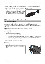
Connection of an additional grounding conductor
In some countries, an additional grounding conductor is generally required. In each case,
observe the locally applicable regulations.
• If an additional grounding conductor is required, connect the one that has an cross-
section of at least 10 mm (see Section 6.2.3, page 31). This prevents touch current in
the event of the grounding conductor on the AC connector bush insert failing.
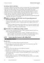
6.2.2
Connecting the Inverter to the Utility Grid
Requirements:
☐ The connection requirements of the grid operator must be met.
☐ The grid voltage must be within the permissible range. The exact operating range of the
inverter is specified in the operating parameters.
Procedure:
1. Disconnect the circuit breaker and secure it against reconnection.
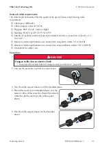
2. Dismantle the AC cable by 50 mm.
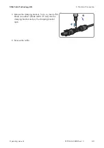
3. Shorten L1, L2, L3 and N by 8 mm each so that the grounding conductor is 8 mm longer. This
ensures that the grounding conductor is the last to be pulled from the screw terminal in the
event of tensile strain.
4. Strip the insulation of L1, L2, L3, N and the grounding conductor 12 mm.
5. In the case of fine stranded wire, L1, L2, L3, N and the grounding conductor are to be fitted
with bootlace ferrules.
Summary of Contents for STP3.0-3AV-40
Page 106: ...www SMA Solar com ...


