SMA Solar Technology AG
5 Installation
Installation Manual
STPS60-IA-xx-13
27
5.5 Opening the Installation Area
Procedure:
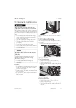
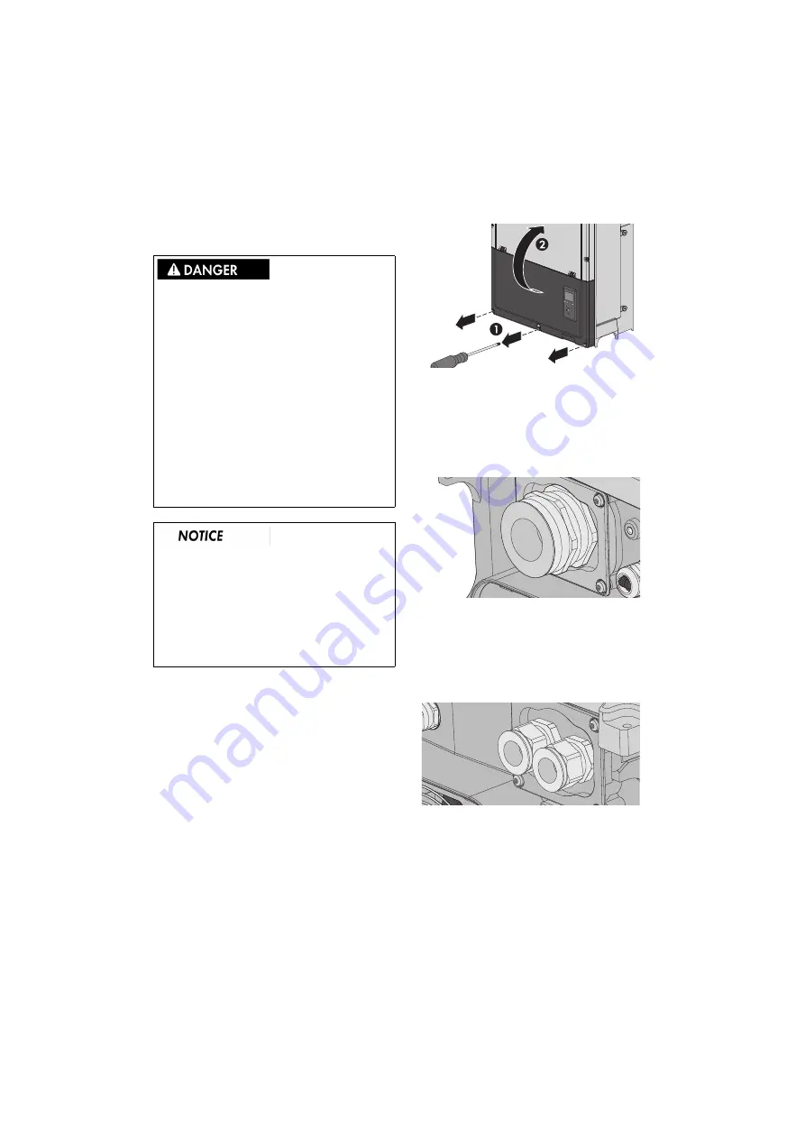
1. To open the cover, loosen the three lower front screws
using a TX 30 screwdriver. The screws are captive
screws and cannot fall out.
2. Raise the cover by 180 degrees. A magnet enables the
cover to stay open.
3. To close the cover, lower it into place and fasten the
three front screws.
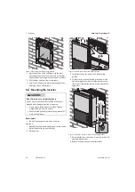
Figure 16: Loosen the screws and lift the cover of the installation
area
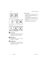
5.6 Enclosure Opening
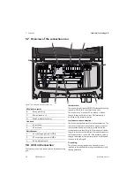
The mounting brackets for the cable glands are already
pre-mounted.
• Always observe the ampacity of cables used
Figure 17: AC cable gland
AC cable requirements:
• Conductor cross-section: 35 mm² to 150 mm²
• Conductor material: Al/Cu
• Cable sheath diameter with supplied cable gland: 46
to 53 mm
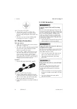
Figure 18: DC cable gland
DC cable requirements:
• Conductor cross-section: 35 mm² to 150 mm²
• Conductor material: Al/Cu
• Cable sheath diameter with supplied cable gland: 18
to 25 mm
Danger to life due to electric shock when live
components or cables of the inverter are touched
High voltages are present in the conductive components
or cables of the inverter. Touching live parts and cables of
the inverter results in death or lethal injuries due to electric
shock.
• Disconnect the product and battery from voltage
sources and make sure it cannot be reconnected
before working on the device.
• Wait five minutes before working on the inverter.
• Observe all safety information of the battery
manufacturer.
• Do not touch non-insulated parts or cables.
• Wear suitable personal protective equipment for all
work on the product.
Damage to the inverter due to electrostatic
discharge
Touching electronic components can cause
damage to or destroy the inverter through
electrostatic discharge.
• Ground yourself before touching any
component.

