SMA Solar Technology AG
5 Installation
Installation Manual
STPS60-IA-xx-13
29
The input and output circuits of the inverter are isolated from
the enclosure.
The configuration of grounding depends on the project and
is the responsibility of the installer.
Fuses and residual-current device (RCD):
For fuse and RCD information, refer to Section
11, page 46. AC fuse rating must not exceed the ampacity
of the conductors used.
Overcurrent protection:
The inverter does not provide overcurrent protection. This
must be provided by the installer (see
Section 11.5, page 50).
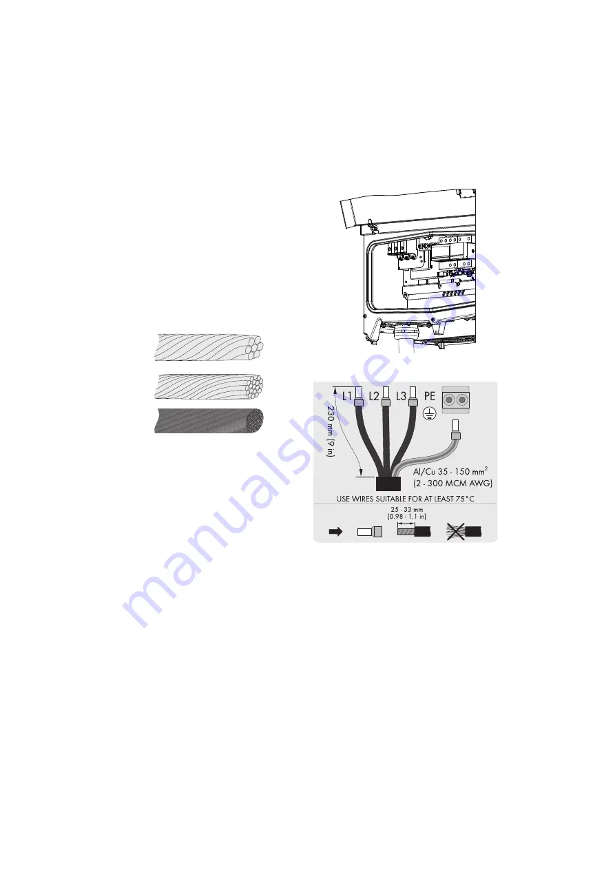
Cable requirements:
Figure 20: Cables with different conductors (from top to bottom):
multi-strand, fine-strand and extra fine-strand
• Cables with multi-strand, fine-strand or extra fine-strand
conductors can be used for AC connection.
• The cables must be suitable for a temperature of at
least 75°C.
• When using fine-strand or extra fine-strand conductors,
bootlace ferrules must be used for the connection.
Procedure:
Figure 21: AC installation area
1. Disconnect the inverter (see Section 8, page 35).
Figure 22: AC cable wire strip
2. Make sure that the protective conductor (PE) is longer
than the grid wires (L1, L2, L3).
3. Strip off all 4 conductors.
4. Insert the cable through the AC cable gland to the
terminal block.
5. Connect the grounding conductor (PE) and the three
grid wires (L1, L2, L3) to the terminal block with the
respective markings. The grounding conductor is
marked with the following symbol.


