background image

11   Technical Data

SMA Solar Technology AG

46

STPS60-IA-xx-13

Installation Manual

11 Technical Data

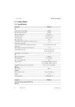
11.1 Specifications

Parameters

STPS60-10

AC

Rated power at nominal voltage

75000 W

Maximum apparent AC power

75000 VA

Maximum reactive power

75000 var

Nominal AC voltage

3 / PE; 400 V ± 10%

AC voltage range

360 V to 530 V

Max. output current 

109 A

AC total harmonic distortion (THD at nominal output power)

≤ 1%

Power factor at rated power

1

Power factor at rated power / adjustable displacement 
power factor

1 / 0 overexcited to 0 underexcited

Stand-by power consumption (for communication)

< 3 W

AC grid frequency / range

50 Hz / 44 Hz to 55 Hz
60 Hz / 54 Hz to 65 Hz

Feed-in phases / connection phases

3 / 3

DC

Maximum charging power

60000 W

DC voltage range

570 V to 1000 V

Max. input current at 660 V

140 A

Surge categories

AC: Overvoltage category III (OVC III),

DC: Overvoltage category II (OVC II)

Integrable DC surge arrester / AC surge arrester

Type II / type II + III (combined)

Efficiency

Max. efficiency

98.8 %

Enclosure

Dimensions (W / H / D)

 740 × 570 × 306 mm

Weight

 77 kg

Acoustic noise level

58 dB(A) (typical)

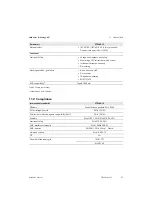
Parameters

STPS60-10

Protection class (according to IEC 62109-1)

I

Electrical

Summary of Contents for STPS60-10

Page 1: ...A xx 13 200906 00 01 Version 1 3 Installation Guide Installationsanleitung Instrucciones de instalación Instructions d installation Istruzioni per l installazione Instrukcja instalacji SUNNY TRIPOWER STORAGE 60 ...

Page 2: ......

Page 3: ...2 Safety 17 2 1 Intended Use 17 2 2 Safety Information 17 3 Product Overview 20 3 1 Front View 20 3 2 DC Load Break Switch 20 3 3 Symbols on the Product 20 3 4 Inverter Type Label 21 3 5 System Overview 22 4 Scope of Delivery 23 5 Installation 23 5 1 Installation Sequence 23 5 2 Environment and Clearances 23 5 3 Mounting the Wall Mounting Bracket 25 5 4 Mounting the Inverter 26 5 5 Opening the Ins...

Page 4: ...de File 34 7 5 Turning on the Alternating Current 34 7 6 Configuring the Fallback 35 8 Disconnecting From Voltage Sources 35 9 Service 36 9 1 Troubleshooting and Repair 36 9 2 Maintenance 45 10 Decommissioning 45 11 Technical Data 46 11 1 Specifications 46 11 2 Compliance 47 11 3 Installation Conditions 48 11 4 Torque Specifications 49 11 5 Specifications for Grid Protection 50 11 6 Technical Data...

Page 5: ...t 55 2 1 Bestimmungsgemäße Verwendung 55 2 2 Sicherheitshinweise 56 3 Produktübersicht 58 3 1 Frontansicht 58 3 2 DC Lasttrennschalter 59 3 3 Symbole auf dem Produkt 59 3 4 Typenschild des Wechselrichters 60 3 5 Systemübersicht 61 4 Lieferumfang 62 5 Installation 62 5 1 Installationsreihenfolge 62 5 2 Umgebung und Abstände 62 5 3 Wandhalterung montieren 64 5 4 Wechselrichter montieren 65 5 5 Insta...

Page 6: ... 7 4 Grid Code Datei 73 7 5 Wechselstrom einschalten 73 7 6 Fallback konfigurieren 74 8 Freischalten 74 9 Service 75 9 1 Fehlersuche und behebung 75 9 2 Wartung 84 10 Außerbetriebnahme 84 11 Technische Daten 85 11 1 Spezifikationen 85 11 2 Konformität 86 11 3 Installationsbedingungen 87 11 4 Drehmomentspezifikationen 88 11 5 Spezifikation für die Netzsicherungen 89 11 6 Technische Daten der Kommun...

Page 7: ... Indicaciones de seguridad 95 3 Vista general del producto 98 3 1 Vista frontal 98 3 2 Interruptor seccionador de potencia de CC 98 3 3 Símbolos del producto 99 3 4 Placa de características del inversor 99 3 5 Vista general del sistema 100 4 Contenido de la entrega 101 5 Instalación 101 5 1 Orden de instalación 101 5 2 Entorno y espacios libres 101 5 3 Montar el soporte mural 103 5 4 Montaje del i...

Page 8: ...red 113 7 5 Activar la corriente alterna 113 7 6 Configuración del procedimiento de emergencia 114 8 Desconexión 114 9 Mantenimiento 115 9 1 Resolución de problemas 115 9 2 Mantenimiento 127 10 Puesta fuera de servicio 127 11 Datos técnicos 128 11 1 Especificaciones 128 11 2 Conformidad 129 11 3 Condiciones de la instalación 130 11 4 Especificaciones del par de apriete 131 11 5 Especificaciones de...

Page 9: ...Utilisation conforme 137 2 2 Consignes de sécurité 138 3 Vue d ensemble des produits 141 3 1 Vue de face 141 3 2 Interrupteur sectionneur DC 141 3 3 Symboles sur le produit 141 3 4 Plaque signalétique de l onduleur 142 3 5 Vue d ensemble du système 143 4 Contenu de la livraison 144 5 Installation 144 5 1 Séquence d installation 144 5 2 Environnement et distances 144 5 3 Montage du support mural 14...

Page 10: ...ier de codes réseau 155 7 5 Mise sous tension AC 155 7 6 Configuration du repli automatique 156 8 Mettez hors tension 156 9 Service 157 9 1 Recherche d erreurs et dépannage 157 9 2 Entretien 166 10 Mise hors service 166 11 Données techniques 167 11 1 Spécifications 167 11 2 Conformité 168 11 3 Conditions d installation 169 11 4 Spécifications de couple 170 11 5 Spécifications pour la protection du...

Page 11: ...e 176 2 2 Avvertenze di sicurezza 177 3 Panoramica del prodotto 180 3 1 Vista frontale 180 3 2 Sezionatore di carico CC 180 3 3 Simboli sul prodotto 180 3 4 Targhetta di identificazione dell inverter 181 3 5 Panoramica del sistema 182 4 Contenuto della fornitura 183 5 Installazione 183 5 1 Ordine d installazione 183 5 2 Ambiente e distanze 183 5 3 Montare il supporto da parete 185 5 4 Montaggio de...

Page 12: ...ol 194 7 4 File del codice di rete 194 7 5 Attivare l alimentazione 194 7 6 Configurazione del fallback 195 8 Disinserire 195 9 Assistenza 196 9 1 Ricerca degli errori 196 9 2 Manutenzione 206 10 Messa fuori servizio 206 11 Dati tecnici 207 11 1 Specifiche 207 11 2 Conformità 208 11 3 Condizioni di installazione 209 11 4 Specifiche di coppia 210 11 5 Specifiche dei fusibili di rete 211 11 6 Dati t...

Page 13: ...ie zgodne z przeznaczeniem 220 2 2 Wskazówki dotyczące bezpieczeństwa 221 3 Opis urządzenia 224 3 1 Widok z przodu 224 3 2 Rozłącznik izolacyjny DC 225 3 3 Symbole na produkcie 225 3 4 Tabliczka znamionowa falownika 226 3 5 Opis systemu 227 4 Zakres dostawy 228 5 Instalacja 228 5 1 Kolejność czynności podczas instalacji 228 5 2 Środowisko i odstępy 228 5 3 Montaż uchwytu ściennego 230 5 4 Montaż f...

Page 14: ...Plik z kodeksem sieci 240 7 5 Włączenie zasilania prądem zmiennym 240 7 6 Konfiguracja trybu awaryjnego 241 8 Odłączenie od zasilania 241 9 Serwis 242 9 1 Diagnostyka i usuwanie usterek 242 9 2 Konserwacja 254 10 Wyłączenie z użytkowania 254 11 Dane techniczne 255 11 1 Specyfikacja 255 11 2 Zgodność urządzenia 256 11 3 Warunki instalacji 257 11 4 Momenty dokręcania 258 11 5 Specyfikacja bezpieczni...

Page 15: ... the installation and commissioning of electrical devices Training in how to deal with the dangers and risks associated with installing and using electrical devices and installations Training in the installation and configuration of IT systems Knowledge of how an inverter works and is operated Knowledge of how batteries work and are operated Knowledge of all applicable laws standards and directive...

Page 16: ...tional Electrotechnical Commission international standards organization IT Isolated Terra LCS Local commissioning and service tool LCS Tool LED Light Emitting Diode LVD Directive Low voltage directive MCB Miniature circuit breaker MPP Maximum Power Point P P is the symbol for active power and is measured in Watts W PCB Printed circuit board PCC Point of Common Coupling point of interconnection The...

Page 17: ... conversions are only permitted with the express written permission of SMA Solar Technology AG permitted Unauthorized alterations will void guarantee and warranty claims and in most cases terminate the operating license SMA Solar Technology AG shall not be held liable for any damage caused by such alterations Any use of the product other than that described in the Intended Use section does not qua...

Page 18: ...ng of hazardous substances e g safety gloves eye and face protection respiratory protection Danger due to ground fault on DC side during operation Due to the transformerless topology of the product the occurrence of ground faults on DC side during operation can lead to irreparable damage Damages to the product due to a faulty or damaged DC installation are not covered by warranty The product is eq...

Page 19: ... hot during operation Touching hot components can cause burns The inverter is to be installed in such a way that hot components cannot be touched After opening the product wait until the components have cooled down Wear suitable personal protective equipment for all work on the product Damage to the inverter due to electrostatic discharge Touching electronic components can cause damage to or destr...

Page 20: ...o recommissioning SMA inverters after the installation of SMA components or power assemblies which cannot be replaced intuitively ensure that the grounding conductor in the inverter is correctly connected The function of the grounding conductor must be ensured and all locally applicable laws standards and directives must be observed F1 F3 F4 F2 OK Home Back Alarm On A DC load break switch INFORMAT...

Page 21: ... without neutral conductor Direct current The product has no galvanic isolation Observe the documentations Observe all documentations supplied with the product WEEE designation Do not dispose of the product together with the household waste but in accordance with the disposal regulations for electronic waste applicable at the installation site The product is suitable for outdoor installation Degre...

Page 22: ...r Up to 20 inverters and 20 batteries can be connection to each SMA Inverter Manager The SMA Inverter Manager handles all communication of the inverters and batteries It serves as central interface for data acquisition systems upload to cloud services and power plant control Local commissioning and service tool LCS Tool The LCS tool is required for the commissioning and servicing of the inverter v...

Page 23: ...e DC cable see Section 5 10 page 30 8 Close the installation area see Section 7 1 page 34 9 Switch on the DC load break switch see Section 7 2 page 34 10 Switch on the battery 11 Finalize commissioning by using the Local Commissioning and Service Tool LCS Tool The tool is available from the download area at www SMA Solar com The hardware requirements for the LCS Tool are PC with WindowsTM 7 and la...

Page 24: ...alling several inverters mounting them side by side in a single row is recommended Contact the supplier for guidelines when mounting inverters in more than one row Ensure adequate clearance at the front for safe installation and service access to the inverter INFORMATION When selecting the installation site ensure that the product and warning messages on the inverter are visible at all times For d...

Page 25: ...he wall mounting bracket in mm Procedure INFORMATION The safety clearances to other objects must be maintained to ensure sufficient air circulation INFORMATION Use of the wall mounting bracket delivered with the inverter is mandatory Warranty claims will expire if the inverter is operated without the wall mounting bracket It is strongly recommended to use all 6 mounting holes ...

Page 26: ...ery 2 Lift the inverter Figure 14 Attach the eye bolts and lift the inverter 3 Locate the slots on the side of the wall mounting bracket 4 On the inverter position the side screws against the wall mounting bracket slots Push the inverter so the side screws slide into the two lower slots and the two upper slots Figure 15 Hook the inverter into the wall mounting bracket 5 Ensure that the four side s...

Page 27: ...able gland DC cable requirements Conductor cross section 35 mm to 150 mm Conductor material Al Cu Cable sheath diameter with supplied cable gland 18 to 25 mm Danger to life due to electric shock when live components or cables of the inverter are touched High voltages are present in the conductive components or cables of the inverter Touching live parts and cables of the inverter results in death o...

Page 28: ...ection The insulation resistance detector performs a measurement of the connected battery resistance to ground before the inverter connects to the utility grid If the resistance is below the grid code set value the inverter will wait and re measure the resistance after a short while If the resistance is above the grid code setpoint the inverter performs a self test and connects to the utility grid...

Page 29: ...s from top to bottom multi strand fine strand and extra fine strand Cables with multi strand fine strand or extra fine strand conductors can be used for AC connection The cables must be suitable for a temperature of at least 75 C When using fine strand or extra fine strand conductors bootlace ferrules must be used for the connection Procedure Figure 21 AC installation area 1 Disconnect the inverte...

Page 30: ...sert the RJ45 connector into the socket of the Ethernet interface 5 10 DC Connection Danger due to ground fault on DC side during operation Due to the transformerless topology of the product the occurrence of ground faults on DC side during operation can lead to irreparable damage Damages to the product due to a faulty or damaged DC installation are not covered by warranty The product is equipped ...

Page 31: ...he connection DC terminal fuse Install a fuse switch disconnector and a Class J UL listed thermal fuse between the inverter and the battery In the event of an error they are able to securely switch off the short circuit current of the battery Grounding The DC terminal must NOT be connected to ground Procedure Figure 26 DC connection area 1 Disconnect the inverter see Section 8 page 35 Figure 27 DC...

Page 32: ...grid parameters are within the specifications during the required period depending on the grid code and in accordance with local standards and directives the inverter starts operating on the utility grid On grid green LED glowing 60 The inverter is connected to the utility grid and feeds into the grid The inverter disconnects from the utility grid in the following cases The inverter recognizes abn...

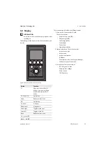
Page 33: ... contains Inverter device type Inverter name Inverter serial number IP Address Serial number of the SMA Inverter Manager Software version of the inverter 3 Actual values This section contains DC voltage and current Phase to phase voltages Phase currents Grid frequency INFORMATION It may take some time until the display responds after switching on Button Function F1 Adjust the contrast level of dis...

Page 34: ...an be provided by SMA and imported via the LCS tool see installation manual of the SMA Inverter Manager LCS Tool 7 4 Grid Code File If the desired grid code is not available or if the LCS Tool displays a warning about incompatible software versions the grid code and software library must be updated on the LCS Tool It is possible to create customer specific grid code files with adjusted set values ...

Page 35: ... described in this section Always adhere to the prescribed sequence Additionally required equipment Current clamp 2 pole voltage detector that does not have its own voltage source Procedure 1 Disconnect the AC miniature circuit breaker from all 3 line conductors and secure against reconnection 2 Switch off the battery 3 Use a current clamp to ensure that no current is present in the DC cables 4 Wa...

Page 36: ...r assistance SMA Service Line If the prescribed action has not identified the malfunction contact Service for further assistance see Section 12 Contact page 52 DC If the prescribed action has not identified the malfunction contact the battery manufacturer for further assistance ID Display Description Measure DN O SMA Se rvice Lin e DC 1 6 Grid undervoltage Grid voltage too low Check voltage and AC...

Page 37: ...range for more than ten minutes frequency and or voltage Check grid frequency grid voltage software version and grid code setting x 41 43 FRT active Fault ride through The inverter has detected that the grid voltage was below or above a certain level If this event is reported several times each day perform onsite grid analysis 44 46 DC componen t step too high DC component in AC current is to high...

Page 38: ...land detected Grid failure If the event reoccurs several times each day contact the responsible grid operator x 64 81 not defined Grid voltage too low Check voltage and AC installation If the voltage is zero check the fuses x ID Display Description Measure DN O SMA Se rvice Lin e DC ...

Page 39: ...ing Warning A repeated occurrence of this message on several consecutive days indicates a general problem in the DC insulation In this case a comprehensive test of the insulation is necessary since even a sudden ground fault during operation cannot be excluded Warning A ground fault during operation can completely destroy the device x x 258 DC bus overvoltage event The DC voltage is too high Make ...

Page 40: ...isplay Description Measure DN O SMA Se rvice Lin e DC 2000 Comm board booted Communication assembly is booting None 2010 Ctrl sw update started The software update of the main CPU has started has finished None 2011 Ctrl sw update ended The software update of the main CPU has started has finished None 2012 2018 The software update failed Restart the software update If an error occurs during the upd...

Page 41: ...tched to the fallback mode after the communication with the SMA Inverter Manager was interrupted None 2056 Fallback ended The inverter has switched back to normal operation after having been in the fallback mode due to a communication disturbance with the SMA Inverter Manager None 2057 Fetching battery limits over TFTP Fetching new battery limits via TFTP has started None 2058 Fetching battery lim...

Page 42: ...rrent measured on AC side is too high Contact the Service x 219 221 Contactor relay failed to close Internal error Voltage measured before and after the relay differs too much Contact the Service x 225 240 Failure in memory Failure in memory EEPROM Restart the inverter If the event persists contact Service x 241 245 Internal communicat ion failure Internal communications fault Restart the inverter...

Page 43: ...t persists ask Service to generate a new grid code file or reselect a standard grid code x 283 Gatedrive error Gatedrive error Restart the inverter If the event persists contact Service x 323 Internal fan error Internal fan error Maximum output power has been reduced If the event repeats contact Service x 370 Manual restart required Inverter has stopped Manual restart is required Restart the inver...

Page 44: ...ace DC surge protection device See SPD replacement instructions for details x 273 AC grid surge protection device error Inverter will continue operation without overvoltage protection Replace AC grid surge protection device See SPD replacement instructions for details x 274 Overvoltage protection device status unknown Restart the inverter If the event persists contact Service x 350 352 Residual cu...

Page 45: ...e the inverter out of the wall mounting bracket slots 3 Lift the inverter off the wall mounting bracket 4 If the inverter is to be stored or shipped pack the inverter Use the original packaging or packaging that is suitable for the weight and dimensions of the inverter and secure the packaging with tie down straps if necessary 5 Dispose of the inverter in accordance with the locally applicable dis...

Page 46: ...splacement power factor 1 0 overexcited to 0 underexcited Stand by power consumption for communication 3 W AC grid frequency range 50 Hz 44 Hz to 55 Hz 60 Hz 54 Hz to 65 Hz Feed in phases connection phases 3 3 DC Maximum charging power 60000 W DC voltage range 570 V to 1000 V Max input current at 660 V 140 A Surge categories AC Overvoltage category III OVC III DC Overvoltage category II OVC II Int...

Page 47: ... monitoring Islanding detection grid failure Active frequency shift Disconnection Three phase monitoring ROCOF SFS RCD compatibility1 Type B 1000 mA Parameters STPS60 10 International standards STPS60 10 Efficiency Peak efficiency standard EN 50530 EC low voltage directive 2014 35 EU EC directive for electromagnetic compatibility EMC 2014 30 EU Certainty EN 62109 1 2010 EN 62109 2 2011 Functional ...

Page 48: ...s G3 at 75 rF Air quality coastal heavy industrial and agricultural zones Must be measured and classified in accordance with ISA S71 04 1985 G3 at 75 RH Vibration 1 G Enclosure protection class IP65 UL 50E enclosure type NEMA 3R Maximum operating altitude above mean sea level 2000 m above sea level power reductions may occur starting at an altitude of 1000 m Installation Avoid constant contact wit...

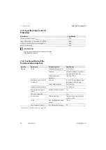
Page 49: ...eter 35 to 95 mm 30 Nm cable sheath diameter 96 to 150 mm C Primary grounding conductor secondary grounding conductor directly to the right of it TX 30 3 9 Nm D DC terminals HX 8 20 Nm cable sheath diameter 35 to 95 mm 30 Nm cable sheath diameter 96 to 150 mm E M32 cable gland Wrench 42 mm 6 Nm Swivel nut of the M32 cable gland Wrench 42 mm 1 8 Nm F M25 cable gland Wrench 33 mm 4 Nm Swivel nut of ...

Page 50: ...llation location Interface Parameters Parameter details Specification Ethernet Cable Cable sheath diameter 2 x 5 to 7 mm Cable typ STP cable Shielded Twisted Pair CAT 5e or SFTP CAT 5e 1 Cable characteristic impedance 100 Ω to 120 Ω RJ45 connector 2 pcs RJ45 for Ethernet Wire size 0 14 to 0 25 mm depending on the design of the RJ45 plug Cable shield termination Via RJ45 plug Galvanic interface ins...

Page 51: ...able 5 12 There are 2 LEDs per interface Table 5 12 LED status Ethernet pin assignment Color standard Cat 5 T 568A Cat 5 T 568B 1 RX Green white Orange white 2 RX Green Orange 3 TX Orange white Green white 4 Blue Blue 5 Blue white Blue white 6 TX Orange6 Green 7 Brown white Brown white 8 Brown Brown INFORMATION Ring topology C in figure 5 5 is only permitted if realized with Ethernet switch suppor...

Page 52: ...rmation in order to provide you with the necessary assistance Inverter device type Inverter serial number Inverter firmware version Special country specific settings of the inverter if applicable Mounting location and altitude of the inverter Display message Type of battery connected Firmware version of the connected battery You can find your country s contact information at https go sma de servic...

Page 53: ...te durchführen Die Fachkräfte müssen über folgende Qualifikation verfügen Ausbildung für die Installation und Inbetriebnahme von elektrischen Geräten Schulung im Umgang mit Gefahren und Risiken bei der Installation und Bedienung elektrischer Geräte und Anlagen Ausbildung für die Installation und Konfiguration von IT Systemen Kenntnis über Funktionsweise und Betrieb eines Wechselrichters Kenntnis ü...

Page 54: ...rte Erde LCS Local Commissioning and Service Tool lokales Inbetriebnahme und Service Tool LED Leuchtdiode NSR Richtlinie Niederspannungsrichtlinie Symbol Erklärung MCB Leitungsschutzschalter MPP Maximum Power Point Punkt maximaler Leistung P P ist das Symbol der Wirkleistung gemessen in Watt W PCB Leiterplatte PCC Point of Common Coupling Netzverknüpfungspunkt Der Punkt im öffentlichen Stromnetz a...

Page 55: ...r von SMA Solar Technology AG zugelassenen eigensicheren Batterie betrieben werden z B STORAGE 67 TS 10 Die Batterie muss über eine separate Trennvorrichtung verfügen Die Batterie muss den vor Ort gültigen Normen und Richtlinien entsprechen und muss eigensicher sein Die Kommunikationsschnittstelle der eingesetzten Batterie muss kompatibel zum Produkt sein Der gesamte Batteriespannungsbereich muss ...

Page 56: ...ender DC Kabel Die DC Kabel die an einer Batterie angeschlossen sind können unter Spannung stehen Das Berühren spannungsführender DC Kabel führt zum Tod oder zu schweren Verletzungen durch Stromschlag Vor Arbeiten das Produkt und die Batterie spannungsfrei schalten und gegen Wiedereinschalten sichern 5 Minuten vor Arbeiten am Wechselrichter warten Alle Sicherheitshinweise des Batterieherstellers e...

Page 57: ...tbögen verursachen Hitzeentwicklungen und Lichtbögen können zu lebensgefährlichen Verletzungen durch Verbrennung führen Vor allen Arbeiten die Batterie über eine externe Trennvorrichtung vom Produkt trennen Alle Sicherheitshinweise des Batterieherstellers einhalten Lebensgefahr durch Stromschlag bei Zerstörung eines Messgeräts durch Überspannung Eine Überspannung kann ein Messgerät beschädigen und...

Page 58: ...Sand Staub und Feuchtigkeit kann der Wechselrichter beschädigt und die Funktion beeinträchtigt werden Den Wechselrichter nur öffnen wenn die Luftfeuchtigkeit innerhalb der Grenzwerte liegt und die Umgebung sand und staubfrei ist Den Wechselrichter nicht bei Sandsturm oder Niederschlag öffnen Bei Unterbrechung und nach Beenden der Arbeiten den Wechselrichter schließen HINWEIS Schutzleiterprüfung vo...

Page 59: ...hr durch hohe Spannungen im Wechselrichter Wartezeit einhalten An den spannungsführenden Bauteilen des Wechselrichters liegen hohe Spannungen an die lebensgefährliche Stromschläge verursachen können Vor allen Arbeiten am Wechselrichter den Wechselrichter immer wie in diesem Dokument beschrieben spannungsfrei schalten Verbrennungsgefahr durch heiße Oberfläche Das Produkt kann während des Betriebs h...

Page 60: ...MA Service Line Auf dem Typenschild finden Sie folgende Informationen Gerätetyp Model Seriennummer Serial No Herstellungsdatum Date of manufacture Gerätespezifische Kenndaten RoHS Kennzeichnung Das Produkt entspricht den Anforderungen der zutreffenden EU Richtlinien CE Kennzeichnung Das Produkt entspricht den Anforderungen der zutreffenden EU Richtlinien UKCA Kennzeichnung Das Produkt entspricht d...

Page 61: ...nager können bis zu 20 Wechselrichter und 20 Batterien angeschlossen werden Der SMA Inverter Manager verwaltet die gesamte Kommunikation der Wechselrichter und der Batterien Er dient als zentrale Anlagenschnittstelle für Datenerfassungssysteme Hochladen in Cloud Dienste und Kraftwerk Leittechnik Lokales Inbetriebnahme und Service Tool LCS Tool Das LCS Tool ist für die Inbetriebnahme und den Servic...

Page 62: ...pitel 5 9 Seite 69 7 DC Kabel anschließen siehe Kapitel 5 10 Seite 69 8 Den Installationsbereich schließen siehe Kapitel 7 1 Seite 73 9 Den DC Lasttrennschalter einschalten siehe Kapitel 7 2 Seite 73 10 Batterie einschalten 11 Inbetriebnahme mittels LCS Tool abschließen Das Tool ist im Download Bereich unter www SMA Solar com erhältlich Hardware Anforderungen für das LCS Tool PC mit WindowsTM 7 od...

Page 63: ...geben Bei Installation mehrerer Wechselrichter die Wechselrichter in einer Reihe nebeneinander montieren Wenden Sie sich für Richtlinien zur Montage von Wechselrichtern in mehreren Reihen übereinander an den Lieferanten An der Frontseite des Wechselrichters zwecks sicherem Einbau und Servicezugang einen ausreichenden Abstand einhalten HINWEIS Bei der Auswahl des Installationsorts sicherstellen das...

Page 64: ...12 Bemaßung der Wandhalterung in mm HINWEIS Für eine ausreichende Luftströmung müssen die Sicherheitsabstände zu anderen Objekten eingehalten werden HINWEIS Die mitgelieferte Wandhalterung muss zwingend verwendet werden Wird der Wechselrichter ohne Wandhalterung betrieben erlischt der Garantieanspruch Es wird dringend empfohlen alle 6 Montagelöcher zu nutzen ...

Page 65: ...heben 3 Die Position der Führungsschlitze an der Seite der Wandhalterung bestimmen 4 Am Wechselrichter die seitlichen Schrauben in die Führungsschlitze der Wandhalterung einsetzen Dazu den Wechselrichter so schieben dass die seitlichen Schrauben in die beiden unteren Führungsschlitze und dann in die oberen Schlitze geführt werden Abbildung 15 Den Wechselrichter in Wandhalterung hängen 5 Sicherstel...

Page 66: ...m Abbildung 18 DC Kabelverschraubung Anforderungen an DC Kabel Leiterquerschnitt 35 bis 150 mm Leitermaterial Al Cu Durchmesser Kabelmantel mit mitgelieferter Kabelverschraubung 18 bis 25 mm 3 Lebensgefahr durch Stromschlag beim Berühren spannungsführender Teile oder Kabel des Wechselrichters An spannungsführenden Teilen oder Kabeln des Wechselrichters liegen hohe Spannungen an Das Berühren spannu...

Page 67: ...gebaute Erkennung des Isolationswiderstands Die Erkennung des Isolationswiderstands führt vor Anschluss an das öffentliche Stromnetz eine Messung des Widerstands der angeschlossenen Batterie zur Erde durch Liegt der Widerstand unterhalb des Sollwerts gemäß den Netzanschlussregeln wartet der Wechselrichter ab und misst den Widerstand nach kurzer Zeit erneut Liegt der Widerstand über dem Sollwert ge...

Page 68: ...pitel 11 5 Seite 89 Kabelanforderungen Abbildung 20 Kabel mit verschiedenen Leitern von oben nach unten mehrdrähtig feindrähtig und feinstdrähtig Für den AC Anschluss können Kabel mit mehrdrähtigen fein oder feinstdrähtigen Leitern eingesetzt werden Die Kabel müssen für eine Mindesttemperatur von 75 C geeignet sein Bei dem Einsatz von Kabeln mit fein oder feinstdrähtigen Leitern müssen für den Ans...

Page 69: ...male Abdichtung einbringen 4 Den RJ45 Steckverbinder in die Buchse der Ethernet Schnittstelle stecken 5 10 DC Anschluss Gefahr durch DC seitigen Erdschluss während des Betriebs Aufgrund der transformatorlosen Topologie des Produkts kann das Auftreten DC seitiger Erdschlüsse während des Betriebs zu irreparablen Schäden führen Schäden am Produkt durch eine fehlerhafte oder beschädigte DC Installatio...

Page 70: ...ung des DC Anschlusses Zwischen Wechselrichter und Batterie einen Sicherungslasttrennschalter und eine Schmelzsicherung der Klasse UL Class J installieren die im Fehlerfall den Kurzschluss Strom der Batterie sicher abschalten Erdung Der DC Anschluss darf NICHT mit Erde verbunden werden Vorgehen Abbildung 26 DC Anschlussbereich 1 Wechselrichter freischalten siehe Kapitel 8 Seite 74 Abbildung 27 DC ...

Page 71: ...er überwacht Wenn die Netzparameter während des erforderlichen Zeitraums innerhalb der Spezifikationen liegen abhängig vom Grid Code und den vor Ort gültigen Normen und Richtlinien beginnt der Wechselrichter den Betrieb am öffentlichen Stromnetz On grid Grüne LED leuchtet 60 Der Wechselrichter ist an das öffentliche Stromnetz angeschlossen und speist in dieses ein Der Wechselrichter trennt sich in...

Page 72: ...hselrichters Name des Wechselrichters Seriennummer des Wechselrichters IP Adresse Seriennummer des SMA Inverter Manager Software Version des Wechselrichters 3 Ist Werte Dieser Abschnitt enthält DC Spannung und Strom Spannungen Phase Phase Phasenströme Netzfrequenz HINWEIS Es kann einige Zeit dauern bis das Display nach dem Einschalten anspricht Taste Funktion F1 Anpassen der Kontraststufe des Disp...

Page 73: ...önnen durch SMA bereit gestellt und über das LCS Tool eingespielt werden siehe Installationsanleitung des SMA Inverter Manager LCS Tool 7 4 Grid Code Datei Wenn der gewünschte Grid Code nicht verfügbar ist oder das LCS Tool eine Warnung wegen inkompatibler Softwareversionen anzeigt müssen der Grid Code und die Softwarebibliothek auf dem LCS Tool aktualisiert werden Es ist möglich kundenspezifische...

Page 74: ...schrieben spannungsfrei schalten Dabei immer die vorgegebene Reihenfolge einhalten Zusätzlich benötigtes Hilfsmittel Zangenampermeter 2 poliger Spannungsprüfer ohne eigene Spannungsquelle Vorgehen 1 Den AC Leitungsschutzschalter von allen 3 Phasen ausschalten und gegen Wiedereinschalten sichern 2 Batterie ausschalten 3 Stromfreiheit mit Zangenamperemeter an allen DC Kabeln feststellen 4 Vor dem Öf...

Page 75: ...onnte wenden Sie sich an den Verteilnetzbetreiber Hotline Wenn die Fehlfunktion durch die empfohlene Maßnahme nicht identifiziert werden konnte wenden Sie sich an den Service siehe Kapitel 12 Kontakt Seite 91 DC Wenn die Fehlfunktion durch die empfohlene Maßnahme nicht identifiziert werden konnte wenden Sie sich an den Batteriehersteller ID Display Beschreibung Maßnahme VNB Hotline DC 1 6 Grid und...

Page 76: ...gung einschalten und prüfen ob das Ereignis erneut eintritt Sichtprüfung sämtlicher DC Kabel und Module durchführen x 40 Grid out of spec Öffentliches Stromnetz liegt länger als zehn Minuten außerhalb des zulässigen Bereichs Frequenz und oder Spannung Netzfrequenz Netzspannung Softwareversion und Grid Code Einstellung prüfen x 41 43 FRT active Fault Ride Through Der Wechselrichter hat festgestellt...

Page 77: ...zausfall offene Phase erkannt Den zuständigen Netzbetreiber kontaktieren wenn das Ereignis mehrmals innerhalb eines Tages auftritt x 62 LOM Island detected Netzausfall Den zuständigen Netzbetreiber kontaktieren wenn das Ereignis mehrmals innerhalb eines Tages auftritt x 64 81 not defined Netzspannung zu niedrig Spannung und AC Installation überprüfen Ist die Spannung gleich Null prüfen Sie die Sic...

Page 78: ...holtes Auftreten dieser Meldung an mehreren Tagen in Folge deutet auf ein generelles Problem in der DC Isolation hin In diesem Fall ist eine umfassende Prüfung der Isolation notwendig da auch ein plötzlicher Erdschluss während des Betriebs nicht ausgeschlossen werden kann Warnung Ein Erdschluss während des Betriebs kann das Gerät vollständig zerstören x x 258 DC bus overvoltage event DC Spannung i...

Page 79: ...m board booted Kommunikationsbaugruppe fährt hoch Keine 2010 Ctrl sw update started Das Software Update des Hauptrechners wurde gestartet ist beendet Keine 2011 Ctrl sw update ended Das Software Update des Hauptrechners wurde gestartet ist beendet Keine 2012 2018 Das Software Update ist fehlgeschlagen Software Update erneut beginnen Falls Fehler beim Update auftreten kontaktieren Sie den Service x...

Page 80: ...ter ist in den Fallback Modus gewechselt nachdem die Kommunikation mit dem SMA Inverter Manager unterbrochen wurde Keine 2056 Fallback ended Der Wechselrichter ist wieder in den Normalbetrieb übergegangen nachdem er sich aufgrund einer Kommunikationsstörung mit dem SMA Inverter Manager im Fallback Modus befand Keine 2057 Fetching battery limits over TFTP Abrufen neuer Batteriegrenzwerte über TFTP ...

Page 81: ...rent high Zu hoher gemessener Strom auf der AC Seite Den Service kontaktieren x 219 221 Contactor relay failed to close Interner Fehler Gemessene Spannung vor und hinter dem Relais weicht zu sehr ab Den Service kontaktieren x 225 240 Failure in memory Störung im Speicher EEPROM Wechselrichter neu starten Wenn das Ereignis andauert den Service kontaktieren x 241 245 Internal communicat ion failure ...

Page 82: ...richter neu starten Wenn der Fehler weiterhin auftritt bitten Sie die Serviceabteilung um die Erstellung einer neuen Grid Code Datei bzw die erneute Auswahl eines Standard Grid Codes x 283 Gatedrive error Gatedrive Fehler Wechselrichter neu starten Wenn das Ereignis andauert den Service kontaktieren x 323 Internal fan error Fehler des internen Lüfters Maximale Ausgangsleistung wurde reduziert Wenn...

Page 83: ... entnehmen Sie den Anweisungen zum SPD Austausch x 273 AC Netz Überspannungsschutzgerät Fe hler Wechselrichter läuft weiter ohne Überspannungsschutz AC Netz Überspannungsschutzgerät austauschen Details entnehmen Sie den Anweisungen zum SPD Austausch x 274 Status des Überspannungsschutzgerätes unbekannt Wechselrichter neu starten Wenn das Ereignis andauert den Service kontaktieren x 350 352 Selbstt...

Page 84: ...rungsschlitzen der Wandhalterung schieben 3 Den Wechselrichter von der Wandhalterung abheben 4 Wenn der Wechselrichter gelagert oder verschickt werden soll den Wechselrichter verpacken Dazu Originalverpackung oder Verpackung verwenden die sich für Gewicht und Größe des Wechselrichters eignet und Verpackung gegebenenfalls mit Spanngurten sichern 5 Wenn der Wechselrichter entsorgt werden soll den We...

Page 85: ...gsfaktor einstellbar 1 0 übererregt bis 0 untererregt Stromverbrauch im Standby Modus für die Kommunikation 3 W AC Netzfrequenz Bereich 50 Hz 44 Hz bis 55 Hz 60 Hz 54 Hz bis 65 Hz Einspeisephasen Anschlussphasen 3 3 DC Maximale Ladeleistung 60000 W DC Spannungsbereich 570 V bis 1000 V Max Eingangsstrom bei 660 V 140 A Überspannungskategorien AC Überspannungskategorie III OVC III DC Überspannungska...

Page 86: ...stands FI Überwachung Inselbetriebserkennung Netzausfall Aktive Frequenzverschiebung Trennung Dreiphasenüberwachung ROCOF SFS RCD Kompatibilität1 Typ B 1000 mA Parameter STPS60 10 Internationale Normen STPS60 10 Wirkungsgrad Spitzenwirkungsgrad Standard EN 50530 EC Niederspannungsrichtlinie 2014 35 EU EC Richtlinie zur elektromagnetischen Verträglichkeit EMV 2014 30 EU Sicherheit EN 62109 1 2010 E...

Page 87: ...Küste in Industriegebieten und landwirtschaftlichen Regionen Muss gemäß ISA S71 04 1985 gemessen und eingestuft werden G3 bei 75 rF Vibrationen 1G Gehäuseschutzklasse IP65 UL 50E Gehäuse Typ NEMA 3R Max Betriebshöhe über NHN Normalhöhennull 2000 m über dem Meeresspiegel ab einer Höhe von 1000 m kann es zu einer Leistungsreduzierung kommen Installation Ständigen Kontakt mit Wasser vermeiden Direkte...

Page 88: ...er Kabelmantel 35 bis 95 mm 30 Nm Durchmesser Kabelmantel 96 bis 150 mm C Primärer Schutzleiter sekundärer Schutzleiter direkt rechts davon TX 30 3 9 Nm D DC Anschlussklemmen HX 8 20 Nm Durchmesser Kabelmantel 35 bis 95 mm 30 Nm Durchmesser Kabelmantel 96 bis 150 mm E M32 Kabelverschraubung Schraubenschlüssel 42 mm 6 Nm Überwurfmutter für M32 Kabelverschraubung Schraubenschlüssel 42 mm 1 8 Nm F M2...

Page 89: ...nien beachten Schnittstelle Parameter Parameterdetails Spezifikation Ethernet Kabel Durchmesser Kabelmantel 2 x 5 bis 7 mm Kabeltyp STP Kabel Shielded Twisted Pair CAT 5e oder SFTP CAT 5e 1 Wellenwiderstand Impedanz der Kabel 100 Ω bis 120 Ω RJ45 Steckverbinder 2 Stück RJ45 für Ethernet Drahtstärke 0 14 bis 0 25 mm je nach Ausführung des RJ45 Steckers Kabelschirmabschluss Über RJ45 Stecker Galvani...

Page 90: ...ro Schnittstelle gibt es 2 LEDs Tabelle 5 12 LED Status Pinbelegung Ethernet Farbstandard Cat 5 T 568A Cat 5 T 568B 1 RX Grün Weiß Orange Weiß 2 RX Grün Orange 3 TX Orange Weiß Grün Weiß 4 Blau Blau 5 Blau Weiß Blau Weiß 6 TX Orange6 Grün 7 Braun Weiß Braun Weiß 8 Braun Braun HINWEIS Ringtopologie C in Abbildung 5 5 ist nur zulässig wenn sie mit einem Ethernet Switch realisiert wird der das Spanni...

Page 91: ...nen gezielt helfen zu können Gerätetyp des Wechselrichters Seriennummer des Wechselrichters Firmware Version des Wechselrichters Ggf länderspezifische Sondereinstellungen des Wechselrichters Montageort und Montagehöhe des Wechselrichters Display Meldung Typ der angeschlossenen Batterie Firmware Version der angeschlossenen Batterie Die Kontaktinformationen Ihres Landes finden Sie unter https go sma...

Page 92: ... solamente especialistas que han de contar con esta cualificación Formación profesional para la instalación y puesta en marcha de equipos eléctricos Formación sobre cómo actuar ante los peligros y riesgos relativos a la instalación y el manejo de equipos eléctricos y plantas Formación profesional sobre la instalación y la configuración de sistemas informáticos Conocimientos sobre los procedimiento...

Page 93: ...o duro Hard Disk Drive IEC Comisión Electrotécnica Internacional International Electrotechnical Commission organización para estándares internacionales IT Sistema de tierras aislado LCS Local Commissioning and Service Tool herramienta local de puesta en marcha y servicio técnico Led Diodo emisor de luz DBT Directiva de baja tensión MCB Disyuntor MPP Punto de máxima potencia Maximum Power Point P P...

Page 94: ...er utilizado en lugares en los que la distancia entre el inversor y equipos sensibles de comunicación por radio sea mayor a 30 m y en los que dispongan de un propio transformador de potencia El producto solo debe utilizarse con una batería de seguridad intrínseca aprobada por SMA Solar Technology AG p ej STORAGE 67 TS 10 La batería debe tener un dispositivo de desconexión separado La batería debe ...

Page 95: ...vitar daños personales y materiales y garantizar el funcionamiento permanente del producto lea detenidamente este capítulo y cumpla siempre las indicaciones de seguridad 1 30 Peligro de muerte por descarga eléctrica por contacto con componentes conductores de tensión o cables del inversor En los componentes conductores o cables del inversor existen altas tensiones El contacto con componentes condu...

Page 96: ...nto el producto no está protegido Asegúrese de que la instalación de CC se lleva a cabo correctamente y que no pueden darse fallos a tierra durante el funcionamiento 7 35 Peligro de lesiones por sustancias tóxicas gases y polvos En algunos casos aislados en el interior del inversor pueden existir sustancias tóxicas gases y polvos debidos a daños en los componentes electrónicos El contacto con sust...

Page 97: ...pere hasta que los componentes se hayan enfriado Utilice equipamientos de protección personal adecuado cuando realice trabajos en el producto 13 6 Daños en el inversor por descarga electrostática Si toca componentes electrónicos puede dañar o destruir el inversor debido a una descarga electrostática Póngase a tierra antes de tocar cualquier componente 13 6 Daños en la junta de la carcasa en caso d...

Page 98: ...ha de los inversores de SMA después de instalar componentes de SMA o subgrupos de potencia que no se puedan sustituir de forma intuitiva asegúrese de que el conductor de protección del inversor esté conectado correctamente El conductor de protección debe funcionar correctamente y deben tenerse en cuenta todas las leyes normativas y directivas locales INDICACIÓN Mantenga los estándares de nivel sup...

Page 99: ...versor existen altas tensiones que pueden causar descargas eléctricas mortales Antes de efectuar cualquier trabajo en el inversor desconéctelo siempre de la tensión tal y como se describe en este documento Peligro de quemaduras por superficies calientes El producto puede calentarse durante el funcionamiento Procure no tocarlo mientras está funcionando Antes de llevar a cabo cualquier trabajo en el...

Page 100: ...l inversor A cada SMA Inverter Manager pueden conectarse hasta 20 inversores y 20 baterías El SMA Inverter Manager se ocupa de todas las comunicaciones con los inversores y las baterías Supone una interfaz única para sistemas de adquisición de datos carga a servicios en la nube y gestión de red LCS Tool Local Commissioning and Service La LCS Tool es necesaria para la puesta en marcha y el mantenim...

Page 101: ... consulte el capítulo 5 9 página 108 7 Conecte los cables de CC consulte el capítulo 5 10 página 108 8 Cierre el área de instalación consulte el capítulo 7 1 página 113 9 Conecte el interruptor seccionador de potencia de CC consulte el capítulo 7 2 página 113 10 Conecte la batería 11 Finalice la puesta en marcha con la LCS Tool La LCS Tool está disponible en la zona de descargas de www SMA Solar c...

Page 102: ...al Si se instalan varios inversores móntelos en fila uno al lado del otro Póngase en contacto con su proveedor para obtener instrucciones sobre cómo montar inversores en más de una fila Compruebe que dispone del espacio libre adecuado en la parte delantera para acceder al inversor con seguridad durante las tareas de instalación y mantenimiento INDICACIÓN A la hora de elegir el emplazamiento para l...

Page 103: ...s del soporte mural en mm Procedimiento INDICACIÓN Mantenga la distancia de seguridad con respecto a otros objetos para garantizar un flujo de aire adecuado INDICACIÓN Es obligatorio utilizar la placa de montaje suministrada con el inversor Si el inversor opera sin el soporte mural la garantía no tiene validez Es altamente recomendable utilizar los seis orificios de montaje ...

Page 104: ... inversor 3 Coloque las ranuras en el lateral de la placa de montaje 4 En el inversor coloque los tornillos laterales frente a las ranuras de la placa de montaje Empuje el inversor de manera que los tornillos laterales se deslicen en las dos ranuras inferiores y en las dos superiores Imagen 15 Enganche el inversor en el soporte mural 5 Asegúrese de que los cuatro tornillos laterales se hayan asent...

Page 105: ...n 18 Racor atornillado para cables de CC Requisitos de los cables de CC Sección de cable de 35 a 150 mm Material de los conductores Al Cu Diámetro del revestimiento del cable con el racor atornillado para cables suministrado de 18 a 25 mm 1 30 Peligro de muerte por descarga eléctrica por contacto con componentes conductores de tensión o cables del inversor En los componentes conductores o cables d...

Page 106: ...tegrada una detección de la resistencia de aislamiento El detector de la resistencia del aislamiento mide la resistencia de la batería conectada a tierra antes de que el inversor se conecte a la red pública Si la resistencia es inferior al valor establecido para el ajuste de red el inversor esperará y volverá a medir la resistencia poco después Si la resistencia es superior al valor de consigna pa...

Page 107: ...na 132 Requisitos del cableado Imagen 20 Cables con diferentes tipos de conductores de arriba abajo de varios hilos de hilo fino y de microhilo Para la conexión de CA se pueden utilizar cables con conductores de varios hilos de hilo fino o de microhilo Los cables deben ser indicados para una temperatura mínima de 75 C Al usar cables con conductores de hilo fino o microhilo necesita utilizar virola...

Page 108: ... del inversor a través de un racor atornillado para cables 3 Corte una ranura en un anillo de goma Coloque el anillo de goma en la unión roscada para garantizar un sellado adecuado 4 Inserte el conectador de enchufe RJ45 en el conector hembra de la interfaz ethernet 5 10 Conexión de CC 7 35 Peligro debido a un fallo a tierra por el lado de la CC durante el funcionamiento Debido a la topología sin ...

Page 109: ...a y un cortacircuitos fusible de la clase UL que en caso de fallo pueda desconectar de forma segura la corriente de cortocircuito de la batería Toma a tierra La conexión de CC NO debe ponerse a tierra Procedimiento Imagen 26 Área de conexión de CC 1 Desconecte el inversor de la tensión consulte el capítulo 8 página 114 Imagen 27 Adhesivos de CC 5 Daños en el inversor por la polarización de los cab...

Page 110: ...ación de uno o varios inversores 6 2 Modos de funcionamiento El inversor tiene cinco modos de funcionamiento indicados mediante ledes Off grid ledes apagados 0 51 En determinadas condiciones operativas el inversor se desconecta automáticamente de la red pública y se apaga Las interfaces de usuario y comunicación permanecen conectadas para que pueda existir comunicación Connecting el led verde parp...

Page 111: ...interna Por causas del funcionamiento Internal inverter event el led verde parpadea 54 El inversor está esperando a que alguna condición interna se encuentre dentro de los límites antes de volver a conectarse a la red pública por ejemplo debido a una temperatura demasiado alta Fail safe el led rojo parpadea 70 Si el inversor detecta un error en sus circuitos durante la autoprueba en el modo de fun...

Page 112: ...uientes elementos Modelo del inversor Nombre del inversor Número de serie del inversor Dirección IP Número de serie del SMA Inverter Manager Versión de software del inversor 3 Valores actuales Esta sección contiene los siguientes elementos Tensión de CC y corriente Tensiones fase a fase Corrientes de fase Frecuencia de red INDICACIÓN La pantalla puede tardar unos minutos en activarse después del e...

Page 113: ...orcionarse registros de datos nacionales específicos del cliente y reproducirse mediante la LCS Tool consulte las instrucciones de instalación del SMA Inverter Manager LCS Tool 7 4 Archivo del código de red Si el código de red deseado no está disponible o si la LCS Tool advierte sobre versiones de software incompatibles el ajuste de red y la biblioteca de software de la LCS Tool deberán actualizar...

Page 114: ...tal y como se describe en este capítulo Siga siempre el orden indicado Herramientas adicionales necesarias Pinza amperimétrica Detector de tensión de 2 polos sin fuente de tensión propia Procedimiento 1 Desconecte el disyuntor de CA de las 3 fases y asegúrelo contra la reconexión accidental 2 Desconecte la batería 3 Con una pinza amperimétrica compruebe que no haya corriente en ninguno de los cabl...

Page 115: ...uidor de la red Si la acción descrita no identifica la causa del mal funcionamiento póngase en contacto con el operador distribuidor de la red Servicio Técnico de SMA Si la acción descrita no identifica la causa del funcionamiento defectuoso póngase en contacto con la asistencia técnica para obtener más ayuda consulte el capítulo 12 Contacto página 134 CC Si la acción descrita no identifica la cau...

Page 116: ...La proporción de CC en la tensión de CA es demasiado alta Para incidencias diarias reiteradas realice un análisis de red in situ x 34 37 Residual current El monitor de corriente residual RCMU ha medido un exceso de corriente Desconecte la CA y la CC y espere hasta que la pantalla se haya apagado Después conecte la CC y la CA y observe si se produce de nuevo la incidencia Realice una revisión visua...

Page 117: ...n de CA x 54 56 DC grid current too high La proporción de CC en la tensión de CA es demasiado alta nivel 2 Para incidencias diarias reiteradas realice un análisis de red in situ x 61 LOM open phase Error de la red detectada una fase abierta Si la incidencia se produce varias veces cada día póngase en contacto con el operador de red x 62 LOM Island detected Error de la red Si la incidencia se produ...

Page 118: ...blecido en las instrucciones de instalación La incidencia podría indicar que no existe conexión del conductor de protección PE Advertencia La aparición reiterada de este mensaje varios días consecutivos indica un problema general en el aislamiento de CC En este caso será necesaria una exhaustiva comprobación del aislamiento puesto que tampoco puede excluirse un fallo a tierra repentino durante el ...

Page 119: ... La tensión de CC es demasiado baja Compruebe el sistema de gestión de batería x 491 Inverter lost communicat ion from battery Fallo de comunicación Compruebe el cableado x x 492 not defined El formato de datos de los parámetros enviados de la batería no es compatible Reinicie el inversor Si el error persiste póngase en contacto con el fabricante de la batería x ID Pantalla Descripción Medida Ope ...

Page 120: ...identificar por ejemplo un cable de ethernet averiado 2051 Link down La conexión de ethernet está desconectada No es necesario llevar a cabo ninguna acción Este error sirve para identificar por ejemplo un cable de ethernet averiado 2052 Get grid code La transmisión del código de red del SMA Inverter Manager al inversor ha comenzado Ninguna 2053 Get grid code done La transmisión del código de red d...

Page 121: ...ación de los nuevos valores límite de la batería a través de TFTP iniciada Ninguna 2058 Fetching battery limits completed Recuperación de los nuevos valores límite de la batería a través de TFTP finalizada con éxito Ninguna 2500 BMS error Error de la gestión avanzada de baterías Póngase en contacto con el fabricante de la batería x 2501 BMS warning Advertencia de la gestión avanzada de baterías Pó...

Page 122: ... antes y después del relé difiere demasiado Póngase en contacto con el servicio técnico x 216 218 Grid measured current high La corriente medida en el lado de CA es demasiado elevada Póngase en contacto con el servicio técnico x 219 221 Contactor relay failed to close Error interno La tensión medida antes y después del relé difiere demasiado Póngase en contacto con el servicio técnico x 225 240 Fa...

Page 123: ... un periodo de 24 horas El inversor intentará reconectarse automáticamente tras un periodo de tiempo determinado Espere hasta 24 horas Si la incidencia 34 se repite realice la acción correspondiente a la incidencia 34 x 282 Invalid grid code Configuración del código de red no válida Reinicie el inversor Si el error persiste pida al servicio técnico un nuevo archivo del código de red o un nuevo cód...

Page 124: ...arranque de CC La carga de la batería es insuficiente para el proceso de arranque Asegúrese de que la batería esté activada Póngase en contacto con el fabricante de la batería x 372 Failsafe timeout reset Reinicio del inversor de forma segura Ninguna ID Pantalla Descripción Medida Ope rado r distri buid or dela red Servicio Técnico de SMA CC ...

Page 125: ...des de conmutación en el inversor Póngase en contacto inmediatamente con el servicio técnico x x 272 Error del descargador de sobretensiones de CC El inversor seguirá funcionamiento sin protección contra sobretensión Sustituya el descargador de sobretensiones de CC Encontrará información más detallada en las instrucciones para cambiar los descargadores contra sobretensión x 273 Error del descargad...

Page 126: ...otencia de CC del inversor La desconexión de la tensión de CC mediante un interruptor seccionador de potencia de CC en la Combiner Box sigue siendo posible No ejecute otras acciones ni actividades de conmutación en el inversor Póngase en contacto inmediatamente con el servicio técnico x 366 Se ha producido un error en la autoprueba del RCMU Póngase en contacto con el servicio técnico x ID Descripc...

Page 127: ... fuera de las ranuras del soporte mural 3 Levante el inversor del soporte mural 4 Si el inversor debe almacenarse o enviarse embálelo Utilice el embalaje original o uno que sea adecuado para el peso y el tamaño del inversor y en caso necesario asegúrelo con cintas tensoras 5 Si debe desechar el inversor hágalo conforme a la normativa local vigente para la eliminación de residuos electrónicos 5 Pel...

Page 128: ...tor de desfase ajustable 1 0 inductivo a 0 capacitivo Consumo de energía en standby solo comunicaciones 3 W Frecuencia de red de CA Rango 50 Hz 44 Hz a 55 Hz 60 Hz 54 Hz a 65 Hz Fases de inyección conexión 3 3 CC Potencia de carga máxima 60000 W Rango de tensión de CC 570 V a 1000 V Corriente de entrada máx con 660 V 140 A Categorías de sobretensión CA Categoría de sobretensión III OVC III CC Cate...

Page 129: ...iente de fugas Detección de funcionamiento en isla pérdida de la red eléctrica Cambio de frecuencia activa Desconexión Monitorización trifásica de la red ROCOF SFS Compatibilidad con RCD1 Tipo B 1000 mA Parámetros STPS60 10 Estándares internacionales STPS60 10 Rendimiento Rendimiento máximo estándar EN 50530 Directiva EC de baja tensión 2014 35 EU Directiva sobre compatibilidad electromagnética CE...

Page 130: ...se G3 a 75 HR Calidad del aire zonas costeras muy industrializadas y agrícolas Debe calcularse y clasificarse según ISA S71 04 1985 G3 con 75 HR Vibraciones 1G Clase de protección de la carcasa IP65 Carcasa tipo UL 50E NEMA 3R Altitud máxima de funcionamiento 2000 m sobre el nivel del mar a partir de 1000 m de altitud puede ocurrir una reducción de potencia Instalación Evite el flujo constante de ...

Page 131: ...le 35 a 95 mm 30 Nm Diámetro del revestimiento del cable 96 a 150 mm C Conductor de protección primario secundario a la derecha TX 30 3 9 Nm D Bornes de conexión de CC HX 8 20 Nm Diámetro del revestimiento del cable 35 a 95 mm 30 Nm Diámetro del revestimiento del cable 96 a 150 mm E Racor atornillado para cables M32 Llave 42 mm 6 Nm Tuerca de unión para racores atornillados para cables M32 Llave 4...

Page 132: ...s de los parámetros Especificación Ethernet Cable Diámetro exterior del cable 2 x 5 a 7 mm Tipo de cable Par trenzado apantallado STP CAT 5e o SFTP CAT 5e 1 Impedancia característica del cable 100 Ω a 120 Ω Conectador de enchufe RJ45 2 unidades RJ45 para ethernet Calibre de cable 0 14 a 0 25 mm en función del enchufe metálico de acoplamiento RJ45 Terminación de la pantalla del cable Mediante enchu...

Page 133: ...abla 5 12 Estado de los ledes Diagrama de pines para ethernet Colores estándar Cat 5 T 568A Cat 5 T 568B 1 RX Verde blanco Naranja blanco 2 RX Verde Naranja 3 TX Naranja blanco Verde blanco 4 Azul Azul 5 Azul blanco Azul blanco 6 TX Naranja6 Verde 7 Marrón blanco Marrón blanco 8 Marrón Marrón INDICACIÓN La topología de anillo C en la imagen 5 5 solo está permitida si se hace con árbol de expansión...

Page 134: ...e de forma eficaz necesitamos que nos facilite estos datos Modelo del inversor Número de serie del inversor Versión de firmware del inversor En su caso configuraciones especiales del inversor para cada país Lugar y altura de montaje del inversor Aviso de la pantalla Tipo de batería conectada Versión de firmware de la batería conectada Puede encontrar la información de contacto de su país en https ...

Page 135: ... être réalisées uniquement par un personnel qualifié Le personnel qualifié doit posséder les qualifications suivantes Formation à l installation et à la mise en service d appareils électriques Formation au comportement à adopter en présence des dangers et des risques inhérents à l installation et à la manipulation d appareils et d installations électriques Formation à l installation et à la config...

Page 136: ...r de disque dur IEC Commission électrotechnique internationale TI Terre isolée LCS Local Commissioning and Service Tool outil de service et de mise en service locale DEL Leuchtdiode DBT directive Directive basse tension MCB Miniature Circuit Breaker disjoncteur miniature MPP Maximum Power Point point de puissance maximale P P est le symbole de la puissance active mesurée en watts W PCB Carte impri...

Page 137: ...agnétiques Conformément à EN 55011 2016 l onduleur peut être exploité uniquement sur les sites où la distance entre l onduleur et les dispositifs de radiocommunication sensibles est supérieure à 30 m et où un transformateur de puissance individuel est utilisé Le produit doit être mis en service uniquement en combinaison avec une batterie à sécurité intrinsèque autorisée par SMA Solar Technology AG...

Page 138: ... il existe des risques résiduels Lisez ce chapitre attentivement et respectez en permanence toutes les consignes de sécurité pour éviter tout dommage corporel et matériel et garantir un fonctionnement durable du produit Danger de mort par choc électrique en cas de contact avec des composants conducteurs ou des câbles de l onduleur Les composants conducteurs ou les câbles de l onduleur sont soumis ...

Page 139: ... Veillez à ce que l installation DC soit réalisée correctement et qu aucun défaut à la terre ne survienne durant le fonctionnement Risque de blessures dû à des substances gaz et poussières toxiques Dans de rares cas des dommages de pièces électroniques peuvent générer des substances gaz et poussières toxiques dans l onduleur Le contact avec des substances toxiques ainsi que l inhalation de gaz et ...

Page 140: ...ues vous pouvez endommager voire détruire l onduleur par décharge électrostatique Reliez vous à la terre avant de toucher un composant Risque d endommagement du joint du boîtier en raison du gel Si vous ouvrez l onduleur quand il gèle le joint pourra être endommagé De l humidité peut donc pénétrer dans l onduleur et l endommager N ouvrez l onduleur que si la température ambiante n est pas inférieu...

Page 141: ...u de modules de puissance SMA ne se remplaçant pas de manière intuitive assurez vous que le conducteur de protection est correctement raccordé dans l onduleur Le conducteur de protection doit être fonctionnel et toutes les lois normes et directives en vigueur sur place doivent être respectées F1 F3 F4 F2 OK Home Back Alarm On A Interrupteur sectionneur DC REMARQUE L interrupteur sectionneur DC peu...

Page 142: ...le produit peut devenir brûlant Évitez tout contact avec l appareil pendant le fonctionnement Laissez le produit refroidir suffisamment avant toute intervention Courant alternatif triphasé sans conducteur neutre Courant continu Le produit ne dispose pas de séparation galvanique Respecter la documentation Suivez toutes les informations données dans les documentations fournies avec le produit Marqua...

Page 143: ...sible de brancher jusqu à 20 onduleurs et 20 batteries sur le SMA Inverter Manager Le SMA Inverter Manager traite toutes les communications avec les onduleurs et les batteries Il crée un point d interface unique pour les systèmes de saisie des données les services d envoi vers un cloud et la commande de centrales électriques Outil de mise en service et de service local LCS Tool Le LCS Tool est req...

Page 144: ... 5 10 page 151 8 Fermez la zone d installation voir chapitre 7 1 page 155 9 Activez l interrupteur sectionneur DC voir chapitre 7 2 page 155 10 Mettez la batterie en marche 11 Effectuez la mise en service à l aide de LCS Tool Le LCS Tool est disponible dans la zone de téléchargement à l adresse www SMA Solar com Exigences matérielles pour LCS Tool Ordinateur avec WindowsTM version 7 ou supérieure ...

Page 145: ...ral En cas d installation de plusieurs onduleurs il est recommandé d installer plusieurs onduleurs sur une même ligne Contactez le fournisseur pour connaître les directives de montage des onduleurs sur plusieurs lignes Veillez à respecter une distance adéquate à l avant pour garantir une installation sûre et l accès au service de l onduleur REMARQUE Lors du choix du lieu d installation s assurer q...

Page 146: ...en mm Procédure Figure 13 Montage du support mural REMARQUE Pour une circulation d air suffisante respectez les distances de sécurité avec les autres objets REMARQUE Il est obligatoire d utiliser le support mural fourni avec l onduleur Le montage de l onduleur sans support mural annule toute possibilité de recours à la garantie Il est fortement recommandé d utiliser les six trous de montage ...

Page 147: ...e l onduleur 3 Repérez les fentes sur le côté du support mural 4 Sur l onduleur insérez les vis latérales dans les fentes du support mural Poussez l onduleur de sorte que les vis latérales glissent dans les deux fentes inférieures puis dans les deux fentes supérieures Figure 15 Accrochage de l onduleur dans le support mural 5 Assurez vous que les quatre vis latérales sont correctement insérées dan...

Page 148: ...câble DC Section de câble 35 à 150 mm Matériau du conducteur Al Cu Diamètre de la gaine du câble avec presse étoupe fourni 18 à 25 mm Danger de mort par choc électrique en cas de contact avec des composants conducteurs ou des câbles de l onduleur Les composants conducteurs ou les câbles de l onduleur sont soumis à de hautes tensions Le contact avec des composants conducteurs ou des câbles de l ond...

Page 149: ...nt L onduleur est muni d un dispositif de détection de résistance d isolement Le détecteur de résistance d isolement effectue une mesure de la résistance entre la batterie raccordée et la terre avant que l onduleur ne se connecte au réseau Si la résistance est inférieure à la valeur de consigne définie d après le code réseau l onduleur attend et remesure la résistance après une courte durée Si la ...

Page 150: ...tégé contre les surintensités Le dispositif de protection correspondant doit être fourni par l installateur voir chapitre 11 5 page 171 Exigences en matière de câbles Figure 20 Câbles aux conducteurs différents de haut en bas multibrins à fils fins et à fils extrafins Pour le raccordement AC les câbles doivent être utilisés avec des conducteurs multibrins à fils fins ou à fils extrafins Les câbles...

Page 151: ...interface Ethernet 5 10 Raccordement DC Risque de défaut à la terre côté DC en cours de fonctionnement De par la topologie sans transformateur du produit l apparition de défauts à la terre côté DC durant le fonctionnement peut entraîner des dommages irréparables L endommagement du produit dû à une installation DC erronée ou endommagée n est pas couvert par la garantie Le produit est doté d un disp...

Page 152: ...lisés Protection par fusibles du raccordement DC Installez un fusible interrupteur sectionneur et un coupe circuit à fusible de classe UL Class J capable de couper en toute sécurité le courant de court circuit en cas de dysfonctionnement entre l onduleur et la batterie Mise à la terre Ne reliez PAS le raccordement DC à la terre Procédure Figure 26 Zone de raccordement DC 1 Déconnectez l onduleur v...

Page 153: ...orsque les paramètres du réseau sont dans les spécifications pendant la durée requise selon le code réseau et les normes et directives locales en vigueur l onduleur commence à alimenter le réseau On grid DEL verte allumée 60 L onduleur est raccordé au réseau électrique public et l alimente L onduleur se déconnecte du réseau électrique public dans les cas suivants L onduleur détecte des conditions ...

Page 154: ...uméro de série de l onduleur Adresse IP Numéro de série du SMA Inverter Manager Version du logiciel de l onduleur 3 Valeurs réelles Cette section contient Tension et courant DC Tension entre phases Courants de phase Fréquence du réseau REMARQUE L activation de l écran peut durer quelques instants après la mise sous tension Touche Fonction F1 Ajuster le niveau de contraste de l écran Utilises les t...

Page 155: ...et chargés dans le LCS Tool voir instructions d installation du SMA Inverter Manager LCS Tool 7 4 Fichier de codes réseau Si le code réseau souhaité n est pas disponible ou si LCS Tool émet un avertissement au sujet de versions logicielles incompatibles le code réseau et la bibliothèque de logiciels doivent être mis à jour sur LCS Tool Il est possible de créer des fichiers de codes réseau personna...

Page 156: ...ez toujours l ordre prescrit Moyen auxiliaire supplémentaire requis Pince ampèremétrique Détecteur de tension à 2 pôles sans sa propre source de tension Procédure 1 Coupez le disjoncteur miniature AC des trois conducteurs de ligne et sécurisez le contre le réenclenchement 2 Arrêtez la batterie 3 Assurez vous de l absence de courant au niveau de tous les câbles DC à l aide d une pince ampèremétriqu...

Page 157: ...rmet pas d identifier le dysfonctionnement adressez vous au gestionnaire du réseau de distribution Service en Ligne de SMA Si l action décrite ne permet pas d identifier le dysfonctionnement contactez le service technique voir chapitre 12 Contact page 173 DC Si l action décrite ne permet pas d identifier le dysfonctionnement adressez vous au fabricant de la batterie ID Écran Description Mesure GRD...

Page 158: ...ce du courant de défaut RCMU a mesuré une surintensité Coupez l alimentation AC et DC puis attendez que l écran s éteigne Remettez l alimentation AC et DC puis observez si l événement se produit de nouveau Inspection visuelle de tous les câbles et panneaux DC x 40 Grid out of spec Le réseau électrique public est hors plage pendant plus de 10 minutes fréquence et ou tension Vérifiez la fréquence du...

Page 159: ...nt réalisez une analyse du réseau sur site x 61 LOM open phase Panne du réseau phase ouverte détectée Si l événement se produit de nouveau plusieurs fois par jour contactez l exploitant de réseau x 62 LOM Island detected Panne du réseau Si l événement se produit de nouveau plusieurs fois par jour contactez l exploitant de réseau x 64 81 not defined Tension du réseau trop basse Vérifiez la tension ...

Page 160: ...de mise à la terre Avertissement L apparition répétée de ce message plusieurs jours de suite indique un problème général dans l isolation DC Dans ce cas un contrôle complet d isolation est nécessaire car un soudain défaut à la terre ne peut être exclu en cours de fonctionnement Avertissement Un défaut à la terre peut complètement détruire l appareil en cours de fonctionnement x x 258 DC bus overvo...

Page 161: ...ie n est pas compatible Redémarrez l onduleur Si l erreur persiste contactez le fabricant de batteries x ID Écran Description Mesure GRD Service en Ligne de SMA DC ID Écran Description Mesure GRD Service en Ligne de SMA DC 2000 Comm board booted Le groupe de communication démarre Aucune 2010 Ctrl sw update started La mise à jour du logiciel de l unité centrale a été lancée est terminée Aucune 2011...

Page 162: ...oué Si l événement survient fréquemment contactez le service technique 2055 Fallback activated L onduleur est passé en mode repli automatique après que la communication avec le SMA Inverter Manager s est interrompue Aucune 2056 Fallback ended L onduleur est repassé en mode de fonctionnement normal après avoir basculé en mode repli automatique en raison d un problème de communication avec le SMA In...

Page 163: ...d current high Courant mesuré sur le côté AC trop élevé Contactez le service technique x 219 221 Contactor relay failed to close Erreur interne La tension mesurée avant et après le relais diffère trop Contactez le service technique x 225 240 Failure in memory Panne de mémoire EEPROM Redémarrez l onduleur Si l événement persiste contactez le service technique x 241 245 Internal communicat ion failu...

Page 164: ...arrez l onduleur Si l événement persiste demandez au Service de générer un nouveau fichier de code réseau ou resélectionnez un code réseau standard x 283 Gatedrive error Erreur de passerelle Redémarrez l onduleur Si l événement persiste contactez le service technique x 323 Internal fan error Erreur de ventilateur interne La puissance de sortie maximale a été réduite Si l événement persiste contact...

Page 165: ...spositif de protection contre les surtensions x 273 Erreur de dispositif de protection contre les surtensions réseau L onduleur continue de fonctionner sans protection contre les surtensions Remplacez le dispositif de protection contre les surtensions réseau AC Pour plus d informations consultez les instructions de remplacement du dispositif de protection contre les surtensions x 274 État du dispo...

Page 166: ...déposer du support mural 4 Si l onduleur doit être stocké ou expédié emballez l onduleur Utilisez pour cela l emballage d origine ou un emballage adapté au poids et à la taille de l onduleur et sécurisez le avec des sangles le cas échéant 5 Si l onduleur doit être éliminé éliminez le conformément aux prescriptions d élimination en vigueur pour les déchets d équipements électriques et électroniques...

Page 167: ...acteur de puissance à la puissance assignée Facteur de déphasage réglable 1 0 inductif à 0 capacitif Consommation d électricité en veille pour la communication uniquement 3 W Fréquence du réseau AC Plage 50 Hz 44 Hz à 55 Hz 60 Hz 54 Hz à 65 Hz Phases d injection Phases de raccordement 3 3 DC Puissance de charge maximale 60000 W Plage de tension DC 570 V à 1000 V Courant d entrée max à 660 V 140 A ...

Page 168: ...llance de la résistance d isolement Surveillance du courant résiduel Détection du réseau en site isolé panne du réseau Déplacement actif de fréquence Séparation Surveillance triphasée ROCOF SFS Compatibilité RCD1 Type B 1000 mA Normes internationales STPS60 10 Rendement Rendement maximal standard EN 50530 Directive basse tension 2014 35 EU Directive CE concernant la compatibilité électromagnétique...

Page 169: ...air zones côtières industrielles lourdes et agricoles Mesure obligatoire et classement selon ISA S71 04 1985 G3 à 75 d humidité relative Vibrations 1G Classe de protection et d étanchéité du boîtier IP65 Type de boîtier UL 50E NEMA 3R Altitude de fonctionnement max au dessus du NMM niveau moyen de la mer 2000 mètres au dessus du niveau de la mer probabilité de puissance réduite à une altitude supé...

Page 170: ...a gaine de câble 35 à 95 mm 30 Nm diamètre de la gaine de câble 96 à 150 mm C Conducteur de protection primaire conducteur de protection secondaire immédiatement à droite TX 30 3 9 Nm D Bornes DC HX 8 20 Nm diamètre de la gaine de câble 35 à 95 mm 30 Nm diamètre de la gaine de câble 96 à 150 mm E Presse étoupe M32 Clé de serrage 42 mm 6 Nm Écrou raccord pour presse étoupe M32 Clé de serrage 42 mm ...

Page 171: ... site Interface Paramètre Détails du paramètre Caractéristiques Ethernet Câble Diamètre de la gaine du câble 2 x 5 à 7 mm Type de câble Paire torsadée blindée STP Cat 5e ou SFTP Cat 5e 1 Impédance caractéristique du câble 100 Ω à 120 Ω Connecteur RJ45 2 pièces RJ45 pour Ethernet Épaisseur du fil 0 14 à 0 25 mm en fonction du modèle de fiche RJ45 Terminaison du blindage du câble Via fiche RJ45 méta...

Page 172: ...es DEL Affectation des broches pour l Ethernet Couleur standard Cat 5 T 568A Cat 5 T 568B 1 RX Vert blanc Orange blanc 2 RX Vert Orange 3 TX Orange blanc Vert blanc 4 Bleu Bleu 5 Bleu blanc Bleu blanc 6 TX Orange6 Vert 7 Marron blanc Marron blanc 8 Marron Marron REMARQUE La topologie en anneau C sur la figure 5 5 n est autorisée que si elle est réalisée avec un commutateur Ethernet prenant en char...

Page 173: ...suivantes pour pouvoir assurer une assistance ciblée Type d onduleur Numéro de série de l onduleur Version du micrologiciel de l onduleur Le cas échéant réglages spéciaux régionaux de l onduleur Lieu et hauteur de montage de l onduleur Message à l écran Type de la batterie raccordée Version du micrologiciel de la batterie raccordée Vous pouvez trouver les coordonnées de votre pays à l adresse suiv...

Page 174: ...ere eseguite esclusivamente da tecnici specializzati Questi ultimi devono disporre delle seguenti qualifiche Addestramento relativo all installazione e alla messa in servizio di apparecchi elettrici Corso di formazione su pericoli e rischi durante l installazione e l uso di apparecchi e impianti elettrici Addestramento all installazione e configurazione di sistemi IT Conoscenze in merito a funzion...

Page 175: ...onale IT Terra con neutro LCS Local Commissioning and Service Tool tool locale di messa in servizio e manutenzione LED Diodo a emissione di luce Simbolo Spiegazione LVD Direttiva sulla bassa tensione Direttiva sulla bassa tensione MCB Interruttore automatico MPP Maximum Power Point punto di massima potenza P P è il simbolo della potenza attiva e si misura in watt W PCB Piastra a circuito stampato ...

Page 176: ...erter corrisponde alla tensione di rete L inverter non è previsto per l utilizzo in locali abitativi e non può assicurare una protezione adeguata della ricezione radio contro interferenze elettromagnetiche L inverter secondo EN55011 2016 può essere utilizzato solo in luoghi in cui la distanza tra l inverter e i dispositivi sensibili di comunicazione radio è maggiore di 30 m e in cui dispone di un ...

Page 177: ...Per evitare danni a cose e persone e garantire il funzionamento duraturo del prodotto leggere attentamente il presente capitolo e seguire in ogni momento tutte le avvertenze di sicurezza Pericolo di morte per folgorazione in caso di contatto con componenti o cavi sotto tensione dell inverter Sui componenti o cavi dell inverter sotto tensione sono presenti tensioni elevate Il contatto con component...

Page 178: ...si che l installazione CC sia eseguita correttamente e che non si presenti una dispersione verso terra durante il funzionamento Pericolo di lesioni a causa di sostanze polveri e gas tossici In rari casi isolati il danneggiamento di componenti elettronici può causare la produzione di sostanze polveri e gas tossici all interno dell inverter Il contatto con sostanze tossiche e l inalazione di polveri...

Page 179: ...ili all inverter per scarica elettrostatica Scaricare la propria carica elettrostatica prima di toccare un componente Danneggiamento della guarnizione del coperchio in caso di gelo In caso di gelo se si apre l inverter è possibile danneggiare la guarnizione del coperchio Ciò può favorire la penetrazione di umidità nell inverter e danneggiarlo Aprire l inverter solo se la temperatura ambiente non è...

Page 180: ... gruppi di potenza SMA la cui sostituzione non è intuitiva accertarsi che il conduttore di protezione sia collegato correttamente nell inverter Il funzionamento del conduttore di protezione deve essere garantito e devono essere rispettate le norme e le direttive vigenti a livello locale F1 F3 F4 F2 OK Home Back Alarm On A Sezionatore di carico CC NOTA Il sezionatore CC può essere fissato nella pos...

Page 181: ...ustioni per contatto con superfici bollenti Durante il funzionamento il prodotto può surriscaldarsi Evitare pertanto il contatto durante il funzionamento Prima di qualsiasi operazione lasciar raffreddare a sufficienza il prodotto Corrente alternata trifase senza conduttore neutro Corrente continua Il prodotto non dispone di una separazione galvanica Rispettare la documentazione Rispettare tutta la...

Page 182: ...ter Manager possono essere allacciati fino a 20 inverter e 20 batterie SMA Inverter Manager gestisce l intera comunicazione degli inverter e delle batterie Funge da interfaccia centrale dell impianto per sistemi di rilevamento dati il caricamento in servizi cloud e la gestione automatizzata della centrale fotovoltaica Messa in servizio locale e tool di assistenza LCS Tool LCS Tool è necessario per...

Page 183: ...cap 5 8 pag 188 6 Collegare i cavi Ethernet v cap 5 9 pag 190 7 Collegare i cavi CC v cap 5 10 pag 190 8 Chiudere l area di installazione v cap 7 1 pag 194 9 Inserire il sezionatore CC v cap 7 2 pag 194 10 Attivare la batteria 11 Concludere la messa in servizio mediente LCS Tool Il tool è disponibile nell area download del sito www SMA Solar com Requisiti hardware per LCS Tool PC con WindowsTM 7 o...

Page 184: ...lla figura 2 8 e sull etichetta del supporto da parete In caso di installazione di più inverter montare gli inverter in una sola fila Contattare il fornitore per conoscere le direttive su come montare gli inverter in più di una fila Contattare il fornitore per conoscere le direttive su come montare gli inverter in più di una fila NOTA Nella scelta del luogo di installazione assicurarsi che le etic...

Page 185: ... parete in mm Procedura Figura13 Montaggio del supporto da parete NOTA Per una ventilazione adeguata è necessario rispettare le distanze di sicurezza dagli altri oggetti NOTA L utilizzo del supporto da parete fornito insieme all inverter è obbligatorio Se l inverter viene messo in servizio senza il supporto da parete la garanzia decade Si raccomanda vivamente di usare tutti i 6 fori di montaggio ...

Page 186: ...i sul lato del supporto da parete 4 Sull inverter posizionare le viti laterali contro gli alloggiamenti sul supporto da parete A tale scopo spingere l inverter come mostrato in modo che le viti laterali scorrano nei due alloggiamenti inferiori e nei due alloggiamenti superiori Figura15 Agganciare l inverter al supporto da parete 5 Assicurarsi che le quattro viti laterali siano fissate saldamente n...

Page 187: ...C Sezione del conduttore da 35 a 150 mm Materiale del conduttore alluminio rame Diametro della schermatura con pressacavo in dotazione da 18 a 25 mm Pericolo di morte per folgorazione in caso di contatto con componenti o cavi sotto tensione dell inverter Sui componenti o cavi dell inverter sotto tensione sono presenti tensioni elevate Il contatto con componenti sotto tensione o cavi dell inverter ...

Page 188: ...to L inverter è dotato di un rilevamento della resistenza di isolamento incorporato Il rilevatore della resistenza di isolamento effettua una misurazione della resistenza a terra della batteria collegata prima che l inverter si colleghi alla rete pubblica Se la resistenza è sotto il codice di rete impostare valore l inverter attende quindi misurare nuovamente la resistenza dopo un breve lasso di t...

Page 189: ...tallatore v cap 11 5 pag 211 Requisiti dei cavi Figura20 Cavo con conduttori diversi dall alto verso il basso a corda rotonda flessibili o flessibilissimi Per il collegamento CA possono essere utilizzati conduttori a corda rotonda flessibili o flessibilissimi I cavi devo essere idonei per una temperatura minima di 75 C Nel caso di impiego di cavi con conduttori flessibili o flessibilissimi devono ...

Page 190: ...a dell interfaccia Ethernet 5 10 Collegamento CC Pericolo causa dispersione verso terra lato CC durante il funzionamento A seguito della topologia del prodotto privo di trasformatore la presenza di dispersioni verso terra sul lato CC durante il funzionamento può causare danni irreparabili I danni al prodotto causati da un installazione CC errata o danneggiata non sono coperti dalla garanzia Il pro...

Page 191: ...bili o flessibilissimi devono essere utilizzati puntalini per il collegamento Protezione del collegamento CC Inserire tra l inverter e la batteria un sezionatore di carico e una valvola fusibile UL Class J che in caso di guasto disinseriscono in modo sicuro la corrente di cortocircuito dalla batteria Messa a terra Il collegamento CC NON deve essere effettuato a terra Procedura Figura26 Punti di co...

Page 192: ...della rete di distribuzione Quando i parametri di rete rientrano nelle specifiche previste per l intervallo di tempo predefinito a seconda del codice di rete e delle norme e direttive valide sul posto l inverter inizia l immissione nella rete pubblica On grid LED verde acceso 60 L inverter è collegato alla rete pubblica e la alimenta L inverter si scollega dalla rete pubblica nei seguenti casi L i...

Page 193: ...er Questa sezione contiene Tipo di inverter Nome inverter Numero di serie dell inverter Indirizzo IP Numero di serie di SMA Inverter Manager Versione firmware inverter 3 Valori effettivi Questa sezione contiene Tensione CC e corrente Tensioni da fase a fase Correnti di fase Frequenza di rete NOTA L attivazione del display dopo l accensione può richiedere un po di tempo Tasto Funzione F1 Regola liv...

Page 194: ...cifici per il cliente possono essere predisposti da SMA e caricati tramite LCS Tool v istruzioni per l installazione di SMA Inverter Manager LCS Tool 7 4 File del codice di rete Se il codice di rete desiderato non è disponibile oppure se LCS Tool segnala l incompatibilità delle versioni software il codice di rete e la libreria del software devono essere aggiornati su LCS Tool È possibile generare ...

Page 195: ...scritto nel presente capitolo Rispettare sempre la sequenza indicata Ulteriore materiale ausiliario richiesto Pinza amperometrica Tester bipolare senza fonte di tensione propria Procedura 1 Disinserire l interruttore automatico CA di tutti e 3 i conduttori esterni e bloccarlo contro il reinserimento accidentale 2 Disattivare la batteria 3 Verificare l assenza di corrente su tutti i cavi CC mediant...

Page 196: ...ento contattare il gestore della rete pubblica di distribuzione per ricevere assistenza Servizio di assistenza tecnica SMA Se l azione prescritta non ha identificato il malfunzionamento contattare il servizio di assistenza tecnica v capitolo 12 Contatti pagina 213 CC Se l azione prescritta non ha identificato il malfunzionamento contattare il produttore della batteria per ricevere assistenza ID Di...

Page 197: ... residua RCMU ha misurato una corrente eccessiva Disinserire sia CC che CA e attendere che si spenga il display Quindi inserire CC e CA e osservare se l evento si ripete Ispezione visiva di tutti i cavi e moduli CC x 40 Grid out of spec La rete pubblica è stata fuori intervallo per oltre 10 minuti frequenza e o tensione Controllare la frequenza di rete la tensione di rete la versione del software ...

Page 198: ...liere ripetute effettuare l analisi di rete in loco x 61 LOM open phase Perdita di rete fase aperta rilevata Se l evento si ripete varie volte al giorno contattare il gestore di rete x 62 LOM Island detected Blackout Se l evento si ripete varie volte al giorno contattare il gestore di rete x 64 81 not defined Tensione di rete troppo bassa Controllare la tensione e l installazione CA Se la tensione...

Page 199: ... messaggio si presenta ripetutamente diversi giorni di seguito significa che è presente un problema generale nell isolamento CC In questo caso è necessario controllare approfonditamente l isolamento in quanto non è possibile escludere una dispersione improvvisa verso terra durante il funzionamento Avvertenza una dispersione verso terra durante il funzionamento può distruggere completamente l appar...

Page 200: ...a batteria non è compatibili Riavviare l inverter Se l errore continua a verificarsi contattare il produttore della batteria x ID Display Descrizione Provvedimento VNB Servizio di assisten za tecnica SMA CC ID Display Descrizione Provvedimento VNB Servizio di assisten za tecnica SMA CC 2000 Comm board booted La temperatura interna dell inverter è troppo alta Nessuna 2010 Ctrl sw update started È s...

Page 201: ...iata Nessuna 2053 Get grid code done La trasmissione del codice di rete di SMA Inverter Manager all inverter è stata conclusa Nessuna 2054 Grid code TFTP failed La trasmissione del codice di rete di SMA Inverter Manager all inverter non è andata a buon fine Se questo evento si verifica frequentemente contattare il servizio di assistenza tecnica SMA 2055 Fallback activated L inverter è passato alla...

Page 202: ...ite della batteria tramite TFTP è stata conclusa correttamente Nessuna 2500 BMS error Errore relativo alla gestione della batteria Contattare il produttore della batteria x 2501 BMS warning Avvertenza relativa alla gestione della batteria Contattare il produttore della batteria x ID Display Descrizione Provvedimento VNB Servizio di assisten za tecnica SMA CC ...

Page 203: ...tecnica SMA x 216 218 Grid measured current high La corrente misurata sul lato CA è troppo elevata Contattare il Servizio di assistenza tecnica SMA x 219 221 Contactor relay failed to close Errore interno La tensione misurata a monte e a valle del relè differisce troppo Contattare il Servizio di assistenza tecnica SMA x 225 240 Failure in memory Guasto nella memoria EEPROM Riavviare l inverter Se ...

Page 204: ...l evento persiste chiedere all Assistenza di generare un nuovo file del codice di rete o riselezionare un codice di rete standard x 283 Gatedrive error Errore comando di gate Riavviare l inverter Se l evento persiste chiamare l assistenza x 323 Internal fan error Errore ventola interna La massima potenza di uscita è stata ridotta Se l evento persiste chiamare l assistenza x 370 Manual Restart requ...

Page 205: ...ll SPD per i dettagli x 273 Errore del dispositivo di protezione da sovratensioni di rete CA L inverter continua a funzionare senza protezione da sovratensioni Sostituire il dispositivo di protezione da sovratensioni di rete CA V le istruzioni per la sostituzione dell SPD per i dettagli x 274 Stato del dispositivo di protezione da sovratensioni sconosciuto Riavviare l inverter Se l evento persiste...

Page 206: ...l supporto da parete 4 Imballare l inverter prima di immagazzinarlo o spedirlo A tale scopo utilizzare l imballaggio originale o una confezione adatta al peso e alle dimensioni dell inverter ed eventualmente assicurare la confezione con delle cinghie 5 Qualora sia necessario smaltire l inverter nel rispetto delle norme per lo smaltimento dei RAEE vigenti nel luogo di installazione Pericolo di usti...

Page 207: ...fasamento regolabile 1 0 induttivo a 0 capacitivo Potenza assorbita in standby solo comunicazione 3 W Frequenza di rete CA Range 50 Hz 44 Hz a 55 Hz 60 Hz 54 Hz a 65 Hz Fasi di immissione Fasi di collegamento 3 3 CC Potenza di carica max 60000 W Range di tensione CC 570 V a 1000 V Corrente d ingresso max 660 V 140 A Categorie di sovratensione CA Categoria di sovratensione III OVC III CC Categoria ...

Page 208: ...la corrente residua Rilevamento rete ad isola blackout Spostamento attivo della frequenza Separazione Monitoraggio trifase ROCOF SFS Compatibilità RCD1 Tipo B 1000 mA Parametro STPS60 10 Norme internazionali STPS60 10 Grado di rendimento Massimo grado di rendimento standard EN 50530 Direttiva CE sulla bassa tensione 2014 35 EU Direttiva CE sulla compatibilità elettromagnetica CEM 2014 30 EU Sicure...

Page 209: ... fortemente industrializzate e agricole Deve essere misurato e classificato secondo ISA S71 04 1985 G3 con 75 um rel Vibrazioni 1G Grado di protezione IP dell involucro IP65 Tipo di cassa UL 50E NEMA 3R Altitudine operativa max s l m 2000 m sul livello del mare a partire da un altitudine di 1000 m è possibile una riduzione di potenza Installazione Evitare un contatto continuo con acqua Evitare l i...

Page 210: ...na da 35 a 95 mm 30 Nm diametro della guaina da 96 a 150 mm C Conduttore di protezione primario conduttore di protezione secondario a destra TX 30 3 9 Nm D Morsetti CC HX 8 20 Nm diametro della guaina da 35 a 95 mm 30 Nm diametro della guaina da 96 a 150 mm E Pressacavo M32 Chiave per dadi da 42 mm 6 Nm Dado a risvolto per pressacavo M32 Chiave per dadi da 42 mm 1 8 Nm F Pressacavo M25 Chiave per ...

Page 211: ...ccia Parametro Dettagli del paramento Specifica Ethernet Cavo Diametro della guaina 2 x 5 a 7 mm Tipo di cavo Cavo STP Shielded Twisted Pair CAT 5e oder SFTP CAT 5e 1 Impedenza caratteristica del cavo 100 Ω a 120 Ω Terminale RJ45 2 pezzi RJ45 per Ethernet Sezione conduttore da 0 14 a 0 25 mm in funzione del connettore RJ45 Terminazione schermatura cavo Mediante connettore RJ45 Isolamento galvanico...

Page 212: ...erfaccia Tabella 5 12 Stato del LED Assegnazion e dei PIN per il collegament o Ethernet Colore standard Cat 5 T 568A Cat 5 T 568B 1 RX Verde bianco Arancione bianco 2 RX Verde Arancione 3 TX Arancione bianco Verde bianco 4 Blu Blu 5 Blu bianco Blu bianco 6 TX Arancione6 Verde 7 Marrone bianco Marrone bianco 8 Marrone Marrone NOTA La topologia ad anello C in Figura 5 5 è solo consentita se è realiz...

Page 213: ... fornire un aiuto mirato necessitiamo dei seguenti dati Tipo di inverter Numero di serie dell inverter Versione firmware dell inverter Eventuali impostazioni nazionali specifiche dell inverter Luogo e altitudine di montaggio dell inverter Messaggio sul display Tipo di batteria collegata Versione firmware della batteria collegata Potete trovare le informazioni di contatto per il vostro paese su htt...

Page 214: ......

Page 215: ......

Page 216: ......

Page 217: ...nny Tripower Storage 60 1 2 Grupa docelowa Opisane w niniejszym dokumencie czynności mogą wykonywać wyłącznie wykwalifikowani specjaliści Specjaliści muszą posiadać następujące kwalifikacje Wykształcenie w zakresie instalacji i uruchamiania urządzeń elektrycznych Odbyte szkolenie w zakresie niebezpieczeństw i zagrożeń mogących wystąpić podczas montażu oraz obsługi urządzeń i instalacji elektryczny...

Page 218: ...e Sunny Tripower Storage 60 Falownik produkt Symbol Objaśnienie Skrót Opis cat5e Skrętka kategorii 5 o poprawionych parametrach służąca do transferu danych DHCP Dynamic Host Configuration Protocol protokół umożliwiający automatyczne przyporządkowanie adresu sieciowego przez serwer DHCP DSL Digital Subscriber Line cyfrowa linia abonenck EMV dyrektywa Dyrektywa dotycząca kompatybilności elektromagne...

Page 219: ...nstalacja jest podłączona do publicznej sieci elektroenergetycznej PSTC Moc W przy standardowych warunkach testowych PV Fotowoltaika ogniwa fotowoltaiczne RCD Wyłącznik różnicowoprądowy RCMU Residual Current Monitoring Unit moduł monitorowania prądu szczątkowego RISO Rezystancja izolacji ROCOF Rate Of Change Of Frequency współczynnik zmiany częstotliwości Skrót Opis Q Symbol mocy biernej mierzonej...

Page 220: ...tałe Falownik może być używany tylko wtedy gdy jego napięcie znamionowe odpowiada napięciu sieci energetycznej Falownik nie jest przeznaczony do stosowania w pomieszczeniach mieszkalnych i nie może zapewnić ochrony odbioru radiowego przed sygnałami zakłócającymi w takich środowiskach Zgodnie z normą EN55011 2016 falownik może być eksploatowany wyłącznie w miejscach w których odległość pomiędzy fal...

Page 221: ...ących na szczeblu innych jednostek administracji państwowej ani przepisów lub norm w zakresie instalacji bezpieczeństwa elektrycznego i użytkowania produktu SMA Solar Technology AG nie ponosi odpowiedzialności za przestrzeganie względnie nieprzestrzeganie tych przepisów lub regulacji w związku z instalacją produktu Tabliczka znamionowa musi znajdować się na produkcie przez cały czas 2 2 Wskazówki ...

Page 222: ...b odniesienie niebezpiecznych dla życia obrażeń ciała wskutek kontaktu z gorącymi lub wyrzuconymi na zewnątrz częściami W przypadku usterki nie wolno dokonywać bezpośrednich ingerencji w falowniku Należy zadbać aby osoby niepowołane nie miały dostępu do falownika Wyłączyć wyłącznik nadmiarowo prądowy AC i zabezpieczyć przed ponownym włączeniem Odłączyć akumulator od produktu za pomocą zewnętrznego...

Page 223: ...rowadzić do uszkodzenia urządzenia pomiarowego i wystąpienia napięcia na jego obudowie Dotknięcie będącej pod napięciem obudowy urządzenia pomiarowego prowadzi do śmierci lub odniesienia ciężkich obrażeń ciała wskutek porażenia prądem elektrycznym Należy stosować urządzenia pomiarowe których zakresy pomiarowe są przystosowane do maksymalnego napięcia AC i DC falownika 0453 Ļ Zagrożenie życia wskut...

Page 224: ...goci może być przyczyną jego uszkodzenia i negatywnie odbić się na jego funkcjonowaniu Falownik wolno otwierać tylko wtedy gdy wilgotność znajduje się w określonym zakresie i jego otoczenie jest wolne od kurzu i piasku Falownika nie wolno otwierać podczas burzy piaskowej lub opadów W razie przerwania i po zakończeniu prac zamknąć falownik WSKAZÓWKA Sprawdzenie przewodu ochronnego przed ponownym wł...

Page 225: ...ć wymagany okres czasu W elementach falownika znajdujących się pod napięciem występuje wysokie napięcie które może doprowadzić do zagrożenia życia wskutek porażenia prądem elektrycznym Przed wykonywaniem jakichkolwiek prac przy falowniku należy odłączyć go spod napięcia zgodnie z opisem zawartym w niniejszym dokumencie Niebezpieczeństwo poparzenia się o gorącą powierzchnię Podczas pracy produkt mo...

Page 226: ...A Na tabliczce znamionowej podane są następujące informacje Typ urządzenia Model Numer seryjny Serial No Data produkcji Date of manufacture Parametry urządzenia Stopień ochrony IP65 Produkt chroniony jest przed wnikaniem pyłu i przed wodą napływającą na obudowę strumieniem z dowolnego kierunku Oznakowanie RoHS Produkt spełnia wymogi stosownych dyrektyw Unii Europejskiej Oznakowanie CE Produkt speł...

Page 227: ...go modułu SMA Inverter Manager można podłączyć maks 20 falowników oraz 20 akumulatorów SMA Inverter Manager zarządza komunikacją falowników i akumulatorów Stanowi on centralny interfejs dla systemów rejestracji danych transferu danych do chmury i sterowania elektrownią Miejscowe narzędzie rozruchowe i serwisowe LCS Tool LCS Tool jest wymagane do uruchomienia i obsługi falowników za pomocą urządzen...

Page 228: ...na 235 7 Podłączenie kabla prądu stałego patrz rozdział 5 10 strona 235 8 Zamknięcie strefy przyłączy patrz rozdział 7 1 strona 240 9 Włączenie rozłącznika izolacyjnego DC patrz rozdział 7 2 strona 240 10 Włączenie akumulatora 11 Zakończenie uruchamiania za pomocą LCS Tool Narzędzie jest dostępne w strefie pobierania na stronie www SMA Solar com Wymaganie sprzętowe programu LCS Tool Komputer PC z ...

Page 229: ...nym W przypadku instalacji kilku falowników zaleca się montowanie ich obok siebie w jednym rzędzie Jeśli falowniki będą montowane w kilku szeregach jeden nad drugim prosimy skontaktować się z dostawcą urządzenia w celu uzyskania odpowiednich wytycznych Należy zapewnić odpowiedni odstęp z przodu falownika aby umożliwić dostęp do niego podczas montażu oraz prowadzeniu konserwacji WSKAZÓWKA Podczas w...

Page 230: ... Wymiary uchwytu ściennego w mm WSKAZÓWKA Należy zachować bezpieczne odstępy od innych obiektów aby zapewnić wystarczającą cyrkulację powietrza WSKAZÓWKA Przy montażu należy koniecznie użyć dołączonego do produktu uchwytu ściennego Zamontowanie falownika bez uchwytu ściennego powoduje utratę gwarancji Należy koniecznie użyć wszystkich 6 otworów montażowych ...

Page 231: ...nie falownika 3 Zlokalizować rowki prowadzące po bokach uchwytu ściennego 4 Wprowadzić boczne śruby w falowniku w rowki prowadzące w uchwycie ściennym W tym celu tak przesunąć falownik aby śruby boczne weszły w dwa dolne a następnie dwa górne rowki Rysunek 15 Zawieszenie falownika w uchwycie ściennym 5 Upewnić się że cztery boczne śruby są pewnie wprowadzone do rowków prowadzących w uchwycie ścien...

Page 232: ...odu Al Cu Średnica płaszcza kabla z dostarczonym przepustem kablowym 18 do 25 mm 1 ă4580 Zagrożenie życia na skutek porażenia prądem w przypadku dotknięcia znajdujących się poda napięciem części lub kabli falownika Na przewodzących napięcie częściach lub kablach falownika występuje wysokie napięcie Dotknięcie przewodzących napięcie części lub kabli falownika prowadzi do śmierci lub odniesienia cię...

Page 233: ...owania rezystancji izolacji Układ monitorowania rezystancji izolacji wykonuje pomiar rezystancji podłączonego akumulatora względem uziemienia przed podłączeniem falownika do publicznej sieci elektroenergetycznej Jeśli wartość rezystancji jest mniejsza niż wartość zadana określona w warunkach przyłączenia do sieci falownik czeka przez krótki czas i ponownie wykonuje pomiar rezystancji Jeśli rezysta...

Page 234: ...zabezpieczenia nadprądowego Jego wykonanie należy do obowiązków instalatora patrz rozdział 11 5 strona 259 Wymagania dotyczące przewodów Rysunek 20 Kable z różnymi żyłami od góry do dołu wielodrutowy cienkodrutowy i bardzo cienkodrutowy Kable z żyłami wielodrutowymi cienkodrutowymi lub bardzo cienkodrutowymi mogą być stosowane do połączeń prądu zmiennego Kable te muszą być przystosowane do pracy w...

Page 235: ...dstawy falownika 3 Wykonać nacięcie w gumowym pierścieniu uszczelniającym Umieścić gumowy pierścień uszczelniający w przepuście kablowym aby zapewnić odpowiednie uszczelnienie 4 Włożyć złącze wtykowe RJ45 do gniazda interfejsu Ethernet 5 10 Przyłącze DC 0453 Ļ Zagrożenie spowodowane zwarciem doziemnym po stronie DC w trakcie eksploatacji Wskutek beztransformatorowej topologii produktu zwarcie dozi...

Page 236: ...topikowy klasy J lista UL W przypadku wystąpienia awarii są one w stanie bezpiecznie wyłączyć prąd zwarciowy akumulatora Uziemienie Złącza DC NIE WOLNO podłączać do uziemienia Sposób postępowania Rysunek 26 Strefa przyłączy DC 1 Odłączyć falownik od zasilania patrz rozdział 8 strona 241 04530Ļ Niebezpieczeństwo uszkodzenia falownika na skutek odwrotnej polaryzacji przewodów prądu stałego Falownik ...

Page 237: ...ia informacji o stanie falownika Za pomocą wyświetlacza nie można konfigurować ani ustawiać parametrów falownika Symbol na wyświetlaczu objaśnia tryby pracy Miejscowe narzędzie rozruchowe i serwisowe LCS Tool LCS Tool umożliwia konfigurowanie jednego lub wielu falowników 6 2 Tryby pracy Falownik ma 5 trybów pracy wskazywanych przez diody LED Off grid diody LED wyłączone 0 51 Stan LED Diody LED Off...

Page 238: ...a dioda LED świeci się 60 Falownik jest połączony z publiczną siecią elektroenergetyczną i oddaje do niej energię elektryczną Falownik rozłącza się od publicznej sieci elektroenergetycznej w następujących przypadkach Falownik wykrył w sieci anomalia w zależności od kodeksu sieci przesyłowej Wystąpiło zdarzenie wewnętrzne Ze względu na warunki eksploatacji Internal inverter event zielona dioda LED ...

Page 239: ...jny falownika Adres IP Numer seryjny urządzenia SMA Inverter Manager Wersja oprogramowania zainstalowanego w falowniku 3 Wartości rzeczywiste Sekcja ta zawiera Napięcie i prąd DC Napięcia międzyfazowe Prądy fazowe Częstotliwość napięcia w sieci WSKAZÓWKA Może upłynąć trochę czasu zanim wyświetlacz zareaguje po włączeniu Przycisk Funkcja F1 Regulacja poziomu kontrastu wyświetlacza Użyć przycisku st...

Page 240: ... przez firmę SMA i importowane za pomocą LCS Tool patrz instrukcja instalacji SMA Inverter Manager LCS Tool 7 4 Plik z kodeksem sieci Jeśli żądany kodeks sieci jest niedostępny lub jeśli narzędzie LCS Tool ostrzega o niezgodności wersji oprogramowania należy zaktualizować kodeks sieci i bibliotekę oprogramowania w narzędziu LCS Tool Użytkownik może utworzyć niestandardowe pliki z kodeksem sieci za...

Page 241: ...hować podaną kolejność wykonywania czynności Dodatkowo potrzebne materiały pomocnicze Amperomierz cęgowy 2 pinowy tester napięcia bez własnego źródła napięcia Sposób postępowania 1 Wyłączyć wyłączniki nadmiarowo prądowe wszystkich 3 faz i zabezpieczyć je przed ponownym włączeniem 2 Wyłączyć akumulator 3 Amperomierzem cęgowym sprawdzić na wszystkich przewodach DC czy nie płynie przez nie prąd 4 Odc...

Page 242: ...kontaktować się z operatorem sieci przesyłowej w celu uzyskania dalszej pomocy Infolinia serwisowa SMA Jeśli zalecana czynność nie pozwoliła określić usterki należy skontaktować się z serwisem patrz rozdział 12 Kontakt strona 261 DC Jeśli zalecana czynność nie pozwoliła określić usterki należy skontaktować się z producentem akumulatora w celu uzyskania dalszej pomocy ID Wyświetlacz Opis Działanie ...

Page 243: ...eci w miejscu instalacji x 34 37 Residual current Wyłącznik różnicowo prądowy RCMU wykrył nadmierny prąd Wyłączyć zasilanie DC i AC i poczekać aż wyświetlacz się wyłączy Następnie włączyć zasilanie DC i AC oraz sprawdzić czy zdarzenie wystąpi ponownie Przeprowadzić kontrolę wzrokową wszystkich kabli DC i modułów DC x 40 Grid out of spec Parametry publicznej sieci elektroenergetycznej częstotliwość...

Page 244: ... etap 2 W przypadku powtarzających się codziennych wystąpień tego zdarzenia wykonać analizę sieci w miejscu instalacji x 61 LOM open phase Awaria sieci wykryto przerwę w jednej fazie Jeśli zdarzenie powtarza się kilka razy każdego dnia należy skontaktować się z operatorem sieci przesyłowej x 62 LOM Island detected Awaria sieci Jeśli zdarzenie powtarza się kilka razy każdego dnia należy skontaktowa...

Page 245: ... podłączenia PE Ostrzeżenie Powtarzanie się tego komunikatu przez kilka kolejnych dni wskazuje na ogólny problem z izolacją DC W takim przypadku konieczne jest przeprowadzenie kompleksowego testu izolacji ponieważ nie można wykluczyć nawet nagłego zwarcia doziemnego podczas pracy Ostrzeżenie Zwarcie doziemne podczas pracy może całkowicie zniszczyć urządzenie x x 258 DC bus overvoltage event Zbyt w...

Page 246: ...zesyłanych parametrów akumulatora jest niezgodne Ponownie uruchomić falownik Jeśli usterka nadal występuje skontaktować się z producentem akumulatora x ID Wyświetla cz Opis Działanie DN O Infolinia serwiso wa SMA DC ID Wyświetla cz Opis Działanie DN O Infolinia serwiso wa SMA DC 2000 Comm board booted Podzespół komunikacyjny uruchamia się Brak 2010 Ctrl sw update started Aktualizacja oprogramowani...

Page 247: ...go z modułu SMA Inverter Manager do falownika Brak 2053 Get grid code done Zakończono transmisję kodeksu sieciowego z modułu SMA Inverter Manager do falownika Brak 2054 Grid code TFTP failed Transmisja kodeksu sieciowego z modułu SMA Inverter Manager do falownika nie powiodła się Jeśli to zdarzenie będzie się często powtarzało należy skontaktować się z serwisem 2055 Fallback activated Po przerwani...

Page 248: ...i granicznych akumulatora przez TFTP zakończone sukcesem Brak 2500 BMS error Awaria modułu zarządzania akumulatorem Skontaktować się z producentem akumulatora x 2501 BMS warning Ostrzeżenie dotyczące modułu zarządzania akumulatorem Skontaktować się z producentem akumulatora x ID Wyświetla cz Opis Działanie DN O Infolinia serwiso wa SMA DC ...

Page 249: ...actor failed to close Błąd wewnętrzny Napięcie zmierzone przed i za przekaźnikiem różni się o zbyt dużą wartość Skontaktować się z serwisem x 216 218 Grid measured current high Prąd zmierzony po stronie AC jest zbyt duży Skontaktować się z serwisem x 219 221 Contactor relay failed to close Błąd wewnętrzny Napięcie zmierzone przed i za przekaźnikiem różni się o zbyt dużą wartość Skontaktować się z ...

Page 250: ... Autotest musi być wykonywany przynajmniej raz w ciągu 24 godzin Brak 281 Too many RCMU events Zbyt wiele zdarzeń dotyczących RCMU w ciągu ostatnich 24 godzin W okresie 24 godzin po wystąpieniu zdarzenia 34 dozwolone są tylko 4 próby automatycznego ponownego włączenia się Falownik będzie automatycznie próbował nawiązać ponowne połączenie po upływie określonego czasu Odczekać do 24 godzin Jeśli zda...

Page 251: ...ne ponowne uruchomienie Ponownie uruchomić falownik Jeśli zdarzenie będzie nadal występować Prosimy skontaktować się z następującą jednostką x 371 Waiting for DC to start Oczekiwanie na warunki uruchomienia DC Poziom naładowania akumulatora jest zbyt niski do uruchomienia Upewnić się że akumulator jest włączony Skontaktować się z producentem akumulatora x 372 Failsafe timeout reset Ponowne uruchom...

Page 252: ...konywać żadnych dalszych czynności ani operacji łączeniowych na falowniku Natychmiast skontaktować się z serwisem x x 272 Usterka ochronnika przepięciowego DC Falownik kontynuuje pracę bez ochronnika przepięciowego Wymienić ochronnik przepięciowy DC Szczegółowe informacje zawiera instrukcja wymiany ochronnika przepięciowego x 273 Usterka ochronnika przepięciowego w sieci AC Falownik kontynuuje pra...

Page 253: ...chamiać rozłącznika izolacyjnego DC falownika Nadal możliwe jest odłączenie napięcia DC za pomocą odpowiedniego rozłącznika izolacyjnego DC w skrzynce Combiner Box Nie wykonywać żadnych dalszych czynności ani operacji łączeniowych na falowniku Natychmiast skontaktować się z serwisem x 366 Autotest wyłącznika różnicowo prądowego RCMU nie zakończył się powodzeniem Skontaktować się z serwisem x ID Op...

Page 254: ...k z uchwytu ściennego 4 Jeśli falownik ma być przechowywany lub wysłany należy go zapakować W tym celu należy użyć oryginalnego opakowania lub opakowania odpowiedniego do ciężaru i rozmiarów falownika i umocować opakowanie przy użyciu pasów transportowych jeśli to konieczne 5 W przypadku utylizacji falownika należy przestrzegać obowiązujących w miejscu instalacji przepisów dotyczących utylizacji z...

Page 255: ...przy mocy znamionowej współczynnik przesunięcia regulowany 1 0 przewzbudzenie do 0 niedowzbudzenie Zużycie energii w stanie oczekiwania do celów komunikacji 3 W Częstotliwość napięcia w sieci AC zakres częstotliwości 50 Hz 44 Hz do 55 Hz 60 Hz 54 Hz do 65 Hz Liczba faz zasilania podłączenia 3 3 DC Maks moc ładowania 60000 W Zakres napięcia DC 570 V do 1000 V Maks prąd wejściowy przy 660 V 140 A Ka...

Page 256: ...tancji izolacji Wyłącznik różnicowo prądowy Wykrywanie trybu wyspowego awaria sieci Aktywne przesunięcie częstotliwości Rozłączenie Monitorowanie trzech faz ROCOF SFS Obsługiwane wyłączniki różnicowo prądowe RCD 1 Typu B 1000 mA Normy międzynarodowe STPS60 10 Sprawność Sprawność szczytowa norma EN 50530 Dyrektywa niskonapięciowa 2014 35 UE Dyrektywa dotycząca kompatybilności elektromagnetycznej EM...

Page 257: ...ietrza strefy przybrzeżne tereny przemysłowe i rolnicze Konieczność wykonania pomiaru i sklasyfikowania wg ISA S71 04 1985 G3 przy wilgotności względnej 75 Drgania 1G Stopień ochrony obudowy IP65 Typ obudowy UL 50E NEMA 3R Maks wysokość miejsca instalacji produktu n p m 2000 m n p m powyżej 1000 m może wystąpić ograniczenie mocy Instalacja Nie wystawiać na ciągły kontakt z wodą Chronić przed bezpo...

Page 258: ...5 do 95 mm 30 Nm średnica płaszcza kabla od 96 do 150 mm C Pierwotny przewód ochronny wtórny przewód ochronny bezpośrednio z prawej strony TX 30 3 9 Nm D Zaciski przyłączeniowe DC HX 8 20 Nm średnica płaszcza kabla od 35 do 95 mm 30 Nm średnica płaszcza kabla od 96 do 150 mm E Przepust kablowy M32 Klucz płaski 42 mm 6 Nm Nakrętka złączkowa do przepustu kablowego M32 Klucz płaski 42 mm 1 8 Nm F Prz...

Page 259: ...arametr Szczegóły dotyczące parametru Specyfikacja Ethernet Kabel Średnica płaszcza kabla 2 x 5 do 7 mm Typ kabla STP ekranowana skrętka kategorii 5e lub SFTP kategorii 5e 1 Impedancja charakterystyczna kabla od 100 Ω do 120 Ω Złącze wtykowe RJ45 2 szt RJ45 do sieci Ethernet Grubość przewodu od 0 14 do 0 25 mm w zależności od wersji wtyczki RJ45 Zakończenie ekranu kabla Za pomocą wtyczki RJ45 Sepa...

Page 260: ...ków Ethernet Kolorystka Kat 5 T 568A Kat 5 T 568B 1 RX Zielony biały Pomarańczowy biały 2 RX Zielony Pomarańczowy 3 TX Pomarańczowy biały Zielony biały 4 Niebieski Niebieski 5 Niebieski biały Niebieski biały 6 TX Pomarańczowy Zielony 7 Brązowy biały Brązowy biały 8 Brązowy Brązowy WSKAZÓWKA Topologia typu pierścień C na rysunku 5 5 jest dozwolona tylko wtedy gdy jest zrealizowana przy użyciu przeł...

Page 261: ...ić niezbędną pomoc potrzebujemy następujących informacji Typ falownika Numer seryjny falownika Wersja oprogramowania sprzętowego falownika Specjalne krajowe ustawienia falownika w stosownym przypadku Miejsce i wysokość montażu falownika Komunikat na wyświetlaczu Typ podłączonego akumulatora Wersja oprogramowania sprzętowego podłączonego akumulatora Dane kontaktowe dla Twojego kraju znajdują się po...

Page 262: ......

Page 263: ......

Page 264: ...www SMA Solar com SMA Solar Technology ...

Reviews: