SMA America, LLC
Electrical Connection
Installation Guide
SB50US-80US-eng-IUS112633
51
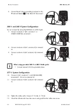
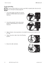
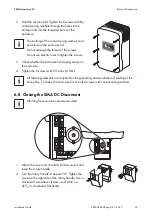
10. Connect the DC device grounding conductor to the PE terminal labeled
in the Sunny Boy.
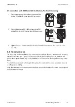
11. Tighten all cables in the AC and DC terminal blocks in the Sunny Boy:
12. Check whether all connections are correctly wired. Carry out a tensile test to see whether all
cables are tight.
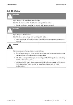
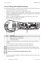
6.5.4 DC Wiring with SMA DC Disconnect
Observe the following procedure to connect the DC cables to the Sunny Boy with SMA DC
Disconnect:
1. Open the AC breaker and secure against turning on again.
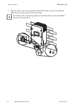
2. Install a
3
⁄
4
in. cable gland in the breakout opening for the DC cables of the SMA DC
Disconnect. The breakout opening is on the left side of the SMA DC Disconnect. Secure the
cable gland to the inner side of the SMA DC Disconnect with the matching locknut.
3. Install a
3
⁄
4
in. cable conduit between the enclosure of the DC disconnect switch and the
breakout opening for DC cables on the SMA DC Disconnect.
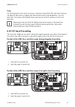
4. Pull the DC cables, the grounding cables of the PV array and the grounding conductor through
the cable conduit and inside the SMA DC Disconnect.
Gray terminal blocks (Weidmüller)
10 … 6 AWG: 18 in-lbs. (2 Nm)
Green terminal blocks (Phoenix)
8 … 6 AWG: 40 in-lbs. (4.5 Nm)
10 AWG: 2 in-lbs. (2.5 Nm)
Fully open the terminal before feeding through the cables.
The SMA DC Disconnect has provisions for up to 4 PV strings. The terminal blocks PV
UNGROUNDED and PV GROUNDED each have 4 connection points. This means that 4
pairs of DC input cables can be connected in parallel.
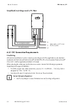
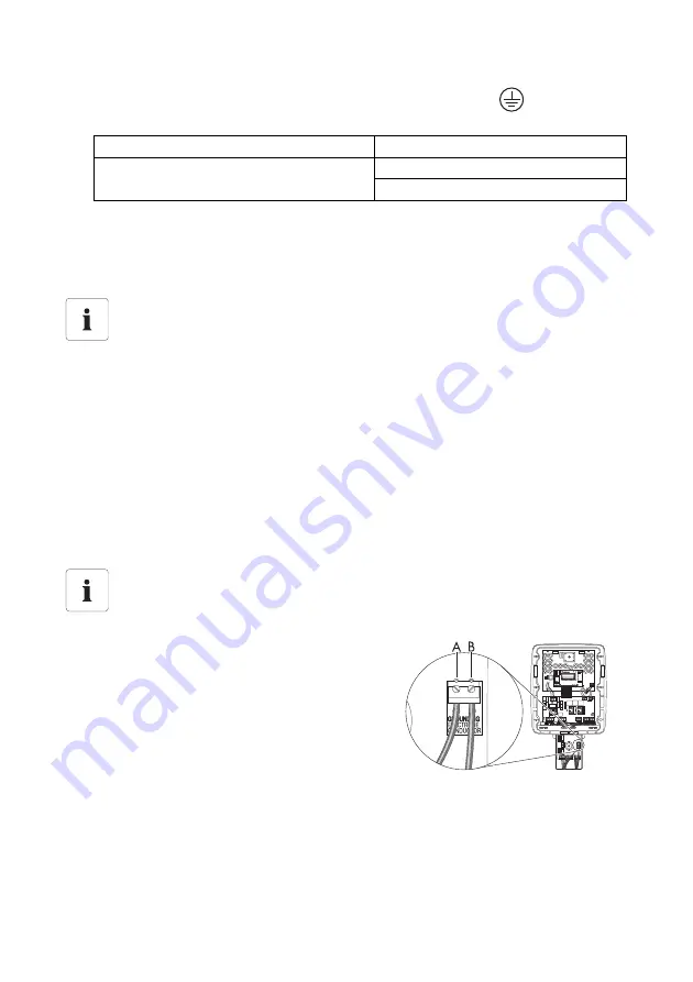
5. Connect the grounding cable of the PV array to the
terminal (A) for the grounding conductor.
6. Connect the grounding conductor to the terminal (B)
for the grounding conductor.

