SMA America, LLC
Electrical Connection
Installation Guide
SB8-10TL-IUS103811
31
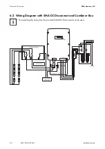
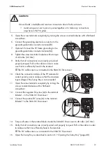
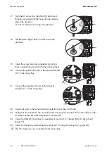
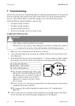
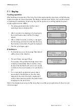
6.5 AC connection
Position
Description
A
Socket for optional communication Piggy-Back (RS485 or wireless)
B
Display
C
Status LEDs
D
Jumper position for verifiying the operation of the fans
E
Power Balancer terminal
F
Flat connection for grounding the cable shield for communication
G
Sunny Boy: Ground terminal (PE)
H
Sunny Boy: Output AC line terminals (N, L1 and L2)
I
Varistor terminal with varistors
K
SMA DC Disconnect: Output AC line terminals (N, L1 and L2)
L
SMA DC Disconnect: Grounding electrode terminal for the connection of:
• Grounding electrode conductor
• DC equipment grounding
• AC equipment grounding
M
SMA DC Disconnect: DC+ terminal
N
SMA DC Disconnect: DC − terminal
O
Sunny Boy: DC − terminal
P
Sunny Boy: DC+ terminal
Q
Terminal for optional communication (RS485)
NOTICE
Danger of fire
Overvoltage may cause cable fire.
• Overcurrent protection for the AC output circuit must be provided in the electrical
installation.
• The size of the overcurrent protection must be maximum 60 A.


