SMA America, LLC
Electrical Connection
Installation Guide
SB8-10TL-IUS103811
39
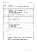
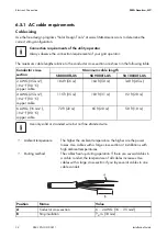
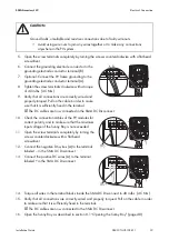
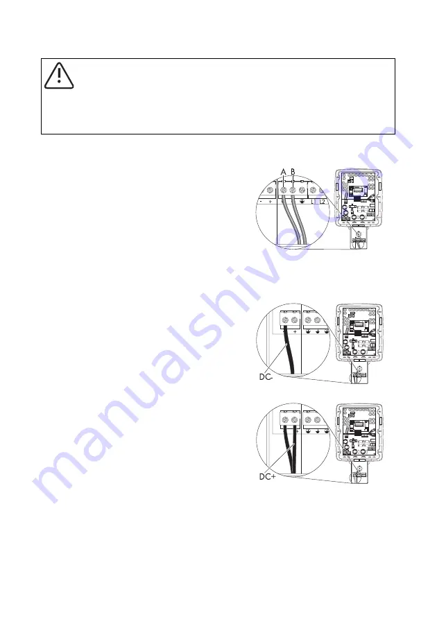
5. Open the screw terminals completely by turning the screws counterclockwise with a flat-head
screwdriver.
6. Connect the grounding electrode conductor to the
grounding electrode conductor terminal (B).
7. Optional: Connect the PV frame grounding to the
grounding electrode conductor terminal (A).
8. Tighten the screw terminals clockwise with a torque
of 40 in‑lbs. (4.5 Nm).
9. Verify that all connections are correctly wired and
properly torqued. Pull on the cable in order to make
sure that it is sufficiently fixed in the terminal.
☑ The DC cables are now connected in the SMA DC Disconnect.
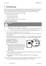
14. Torque all wires in the terminal blocks inside the SMA DC Disconnect to 40 in-lbs. (4.5 Nm).
15. Verify that all connections are correctly wired and properly torqued. Pull on the cable in order
to make sure that it is sufficiently fixed in the terminal.
☑ The DC cables are now connected to the SMA DC Disconnect.
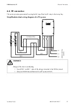
16. Open the Sunny Boy as described in section 8.1 ”Opening the Sunny Boy” (page 48).
CAUTION
Ground faults, unreliable and resistive connections due to faulty wire nuts.
• Avoid using wire nuts to join any wires together or to make any connections
anywhere in the PV system.
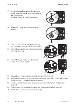
10. Check the connection cables of the PV modules for
correct polarity and to make sure that the maximum
input voltage of the Sunny Boy is not exceeded.
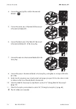
11. Open the screw terminals completely by turning the
screws counterclockwise with a flat-head
screwdriver.
12. Connect the negative DC wires (A) to the terminal
labeled – in the SMA DC Disconnect.
13. Connect the positive DC wires (A) to the terminal
l in the SMA DC Disconnect.

