Sunny Boy 2000
Technical Description
SB2000-11:EE
- 11 -
SMA Regelsysteme GmbH
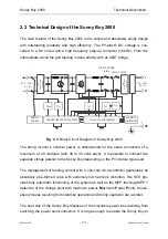
2.3 Technical Design of the Sunny Boy 2000
The main feature of the Sunny Boy 2000 is the simple and absolutely sturdy design
with outstanding reliability and high efficiency. The PV-plant’s DC voltage is con-
verted to a DC circuit with a high frequency step-up converter (16 kHz). From this
intermediate circuit the grid feeding is done directly with an IGBT bridge.
MSD 1
PE
L
N
mains bridge
relay
mains relay
filter
surge v
o
ltage
protection
filter
surge v
oltage
protection
195...253 V
50 Hz
sequential control system
board
supply
current control system
modem
(optional)
MSD 2
125 V...500 V
0...10 A
R
ISO
V
PV
I
AC
f
AC
V
AC
Fig. 2.1: Block Circuit Diagram of Sunny Boy 2000
The string inverter’s nominal power is dimensioned for the serial connection of a
maximum of 20 modules (with 36 to 40 cells each). It is possible to connect two
separate strings parallel to the Sunny Boy depending on the PV-module type used.
The management of feeding current with a one-chip micro-controller guarantees an
absolutely sine-formed curve with extremely low harmonic distortion. The SCS pro-
vides fully automatic functioning of the system as well as the MPP-tracking (MPP =
detection of the voltage point with maximum power, Maximum Power Point). Unnec-
essary losses resulting from stand-by operation and during operation are avoided.
The heat sink of the Sunny Boy disposes of the inevitable power loss resulting from
switching the power semiconductors. It is large enough to enable the Sunny Boy to

