Sunny Boy 2000
Technical Description
SB2000-11:EE
- 30 -
SMA Regelsysteme GmbH
4 Commissioning
Do not put anything on top of the inverter case during operation.
The heat sink on top of the Sunny Boy can have temperatures above
80°C. Danger of burning.
Make sure that all remaining openings for cable insertion at the bottom of
the Sunny Boy have been closed with the seals included in delivery.
First switching on
The Sunny Boy 2000 can be put into operation as soon as it has been connected
electrically and the grounding of the PV-panel’s metal frame has been checked.
•
Connect the inverter to the grid by switching on the fuse of the phase the
inverter is connected to.
The Sunny Boy will begin operation as soon as the input voltage is sufficient. How
much power the Sunny Boy feeds to the grid depends on the amount of PV power
supplied by the PV-panel.
When designing the Sunny Boy SMA kept the internal consumption as low as possi-
ble. The Sunny Boy requires a maximum of 7 W out of the PV power supplied by the
PV-panel.
Please note that despite an extremely low radiation the PV-panel is under load due
to the inverter’s internal consumption. The real open circuit voltage is only produced
with higher solar radiation when the internal consumption is negligible compared to
the power supplied by the PV-panel.
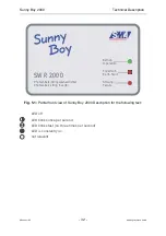
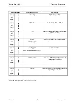
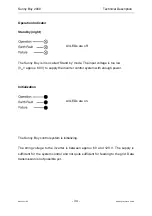
The inverter’s operating condition is indicated with the 3 LEDs on the front - a de-
tailed description will be given in chapter 5: ‘Operation and Failure Indication LEDs’.

