Electrical Connection
SMA Solar Technology AG
16
SB3300TLHC-IEN094121
Installation Guide
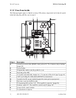
5.1.2 View from Inside
The following diagram gives a schematic overview of the various components and connection points
inside the Sunny Boy with the cover removed:
Object
Description
A
Socket for communication (RS485, radio), section 5.5 ”The Communications Interface”
(page 23)
B
Sunny Display
C
PE (protective earth) connecting cable for cover
D
Operating status LEDs
E
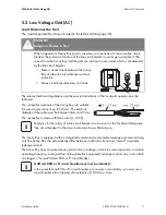
Connection terminals (AC), chapter 5.2.1 ”Connection of the AC Output” (page 18)
F
Tab for grounding the cable shield with RS485 communication
G
Socket for the PLC power module (required for mains grid communication)
H
Electronic Solar Switch (ESS) socket
I
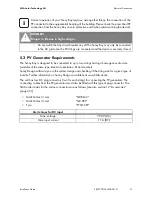
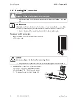
PV input plugs (DC), section 5.3.1 ”PV string (DC) connection” (page 20)
J
Varistors, section 9.1 ”The red LED is continuously lit” (page 32)
K
Jumper slot for communication
L
Communication connector


