background image

SMA Solar Technology AG

Electrical Connection

Installation Guide

SB3300TLHC-IEN094121

23

5.5 The Communications Interface

The communication interface is used to communicate with SMA communication devices (e.g. Sunny 
Boy Control, Sunny WebBox) or a PC with appropriate software (e.g. Sunny Data Control). 
Depending on the selected communication interface, up to 2500 inverters can be interconnected. 
Detailed information on this topic can be found in the communication device manual, the software or 
on the Internet at www.SMA.de/en.
For the installation of the communication interfaces there are the following possibilities: 

• RS485, Funk Piggy-Back (see section 5.5.1 ”Connection RS485, Radio Piggy-Back” 

(page 24))

The detailed wiring diagram for each communication interface can be found in the communication 
device manual. This wiring diagram includes the following information:

• Details on the required cable type
• Which of the inverter's connections are used
• Whether jumpers need to be mounted, and if so, which jumpers
• Whether the PE needs to be connected to the cable shield

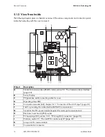
The next pages will describe the following:

• The housing feed-throughs for the communication interface
• The permitted cable route in the Sunny Boy
• The location of the PE connector
• The location of the screw terminals for connecting the communication wires
• The location of the jumper slots
• The location of the interface port
• The location of the interface port for the PLC power module and the Powerline modem

Summary of Contents for SUNNY BOY 3300TL HC

Page 1: ...PV Inverter SUNNY BOY 3300TL HC Installation Guide SB3300TLHC IEN094121 IME SB33TLHC Version 2 1 EN...

Page 2: ......

Page 3: ...Sunny Boy 9 3 2 External dimensions 9 4 Mounting 10 4 1 Selecting the Mounting Location 10 4 2 Mounting the Sunny Boy 12 5 Electrical Connection 14 5 1 Overview Connection Area 14 5 1 1 View from Bel...

Page 4: ...ny Boy 30 8 Maintenance and Cleaning 31 8 1 Cleaning the Cooling Fins 31 8 2 Check the Electronic Solar Switch for wear 31 9 Troubleshooting 32 9 1 The red LED is continuously lit 32 9 1 1 Checking th...

Page 5: ...l where it will be accessible at all times 1 1 Validity This manual is valid for the Sunny Boy 3300TL HC 1 2 Target group This manual is intended for the electrician 1 3 Additional Information You wil...

Page 6: ...ot avoided will result in death or serious injury WARNING WARNING indicates a hazardous situation which if not avoided could result in death or serious injury CAUTION CAUTION indicates a hazardous sit...

Page 7: ...are installed and on the weather rain snow flows from the cells to ground This operational leakage current is not to exceed a value of 50 mA When designing the PV system ensure that the values comply...

Page 8: ...ulled out the Sunny Boy only provides protection degree IP21 The Sunny Boy is then no longer protected against water and contamination with dirt In order that the protection level IP65 is also provide...

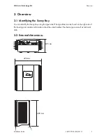
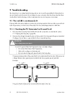
Page 9: ...iew 3 1 Identifying the Sunny Boy You can identify the Sunny Boy using the type label The type label can be found on the right side of the housing and contains information about the serial number the...

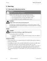
Page 10: ...y Boy to direct sunlight so as to avoid power reduction due to excessive heating DANGER Danger to life due to fire or explosion Despite careful construction a fire can occur with electrical devices Do...

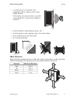
Page 11: ...ving area Vertical installation or tilted backwards by max 45 Install at eye level to allow operating modes to be read at all times Never install the device with a forward tilt Do not install horizont...

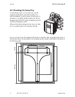
Page 12: ...the bracket using 8 mm x 50 mm hexagon bolts to DIN 571 standard stainless steel type and with wall plugs type SX10 When selecting the mounting materials be sure to take into account the weight of th...

Page 13: ...se the wall bracket as a drilling template 2 Now hang the Sunny Boy onto the wall bracket 2 using its upper mounting plate so that it cannot be moved sideways 3 Fix the Sunny Boy onto its bracket by s...

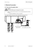
Page 14: ...omplete wiring for a Sunny Boy is shown schematically in the following figure NOTICE Electrostatic discharges can damage the Sunny Boy Internal components of the Sunny Boy can be irreparably damaged b...

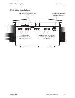
Page 15: ...n Guide SB3300TLHC IEN094121 15 5 1 1 View from Below Plug and socket connector for connection of the solar modules Electronic Solar Switch ESS socket AC plug for the mains supply connection Cable ope...

Page 16: ...Interface page 23 B Sunny Display C PE protective earth connecting cable for cover D Operating status LEDs E Connection terminals AC chapter 5 2 1 Connection of the AC Output page 18 F Tab for groundi...

Page 17: ...nts in normal operation In certain operating states e g during self test of the protective equipment leakage currents may occur which can trigger a normal 30 mA RCD or FI circuit breaker DANGER Danger...

Page 18: ...connection switch the line circuit breaker to its Off position make sure it cannot be switched back on and test to make sure no voltage is present 3 Remove the screws that secure the enclosure of the...

Page 19: ...V generators must also be fitted with this type of plug connector The SMA order codes for the various connectors are as follows see also section 12 Accessories page 39 Correct operation of your Sunny...

Page 20: ...onnection Area page 14 DANGER Danger to life due to high voltages on the Sunny Boy Before connecting the PV generator ensure that the line circuit breaker is switched off Use of Adaptors Adaptors bran...

Page 21: ...witch in the socket on the underside of the Sunny Boy NOTICE Exceeding the maximum input voltage can destroy the Sunny Boy If the voltage of the PV modules exceeds the maximum input voltage of the Sun...

Page 22: ...OTICE Manipulating the connector in the handle can damage the Electronic Solar Switch The connector within the handle must remain movable in order to ensure proper contact Tightening the screw voids a...

Page 23: ...Back see section 5 5 1 Connection RS485 Radio Piggy Back page 24 The detailed wiring diagram for each communication interface can be found in the communication device manual This wiring diagram includ...

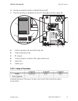
Page 24: ...e Radio Piggy Back 6 Lay the cable in area B as shown in the figure to the right 7 Ground the cable shield at the PE connector C if the connection plan of the communication device indicates this as ne...

Page 25: ...Sunny Boy page 30 5 5 2 Jumper Functions A detailed description of the jumper functiosn can be found in the communication device documentation A Enclosure openings in the base of the Sunny Boy B Cable...

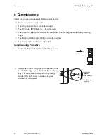
Page 26: ...the underside of the housing are sealed with protecting caps The Electronic Solar Switch ESS is correctly attached The line circuit breaker is correctly rated Commissioning Procedure 1 Switch the line...

Page 27: ...r 5 seconds or when you tap again the current input voltage and the input power are displayed After a further 5 seconds or when you tap again the total energy produced and the time the Sunny Boy has b...

Page 28: ...unny Boy There is a danger of damage to the inverter resulting from excessive DC input voltage Green Red Yellow Status Glows continuously Is not glowing Is not glowing OK feeding operation Glows conti...

Page 29: ...f there is a voltage present check the installation NOTICE Electrostatic discharges can damage the Sunny Boy Internal components of the Sunny Boy can be irreparably damaged by electrostatic discharge...

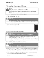
Page 30: ...itch the line circuit breaker to the On position 7 Now check whether the LED display on the Sunny Boy indicates that the device is functioning correctly NOTICE Manipulating the connector in the handle...

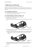
Page 31: ...he Electronic Solar Switch for wear To check the Electronic Solar Switch for wear proceed as follows 1 Remove the Electronic Solar Switch 2 Check whether metal tongues inside the connector have a brow...

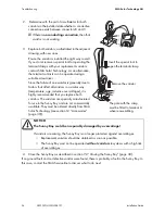
Page 32: ...erator for Ground Fault 1 Disconnect the Sunny Boy from both the DC and AC connections as described in section 7 1 Opening the Sunny Boy page 29 2 Measure the voltages between the plus and minus pole...

Page 33: ...1 Opening the Sunny Boy page 29 Result Measure You have found a ground fault The installer of the PV generator must remedy the ground fault in the affected string before you may reconnect the string...

Page 34: ...ge inductive overvoltages it is highly recommended that you replace both varistors The varistors are specially manufactured for use in the Sunny Boy and are not commercially available They must be ord...

Page 35: ...10 2 Packaging If possible always package the Sunny Boy in the original packaging If this is no longer available you can also use an equivalent box that fulfills the following requirements Suitable f...

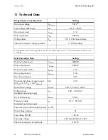
Page 36: ...the maximum input voltage Grid Connection Data Setting Nominal output power PACnom 3000 W Max output power PACmax 3300 W Nominal output current IACnom 13 A Max output current IAC max 16 A Max fuse pr...

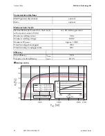
Page 37: ...ature range 25 C 60 C Extended humidity range 0 100 Extended air pressure range 70 kPa 106 kPa Transport of type E Class 2K3 Temperature range 25 C 70 C Operating temperature range 25 C 60 C Max opera...

Page 38: ...Electronic Solar Switch Electrical lifetime in the event of a short circuit with a nominal current of 30 A min 50 switching processes Maximum switching current 30 A Maximum switching voltage 800 V Max...

Page 39: ...WR TV7 Electronic Solar Switch ESS handle replacement part ESS HANDLE 03 RS485 upgrade kit RS485 interface 485PB MS NR Radio upgrade kit Radio Piggy Back for upgrading a Sunny Boy for communication wi...

Page 40: ...ng information in order to provide you with the necessary assistance Inverter type Type and number of modules connected Communication Series number of the Sunny Boy Blink code or display of the Sunny...

Page 41: ...SMA Solar Technology AG Contact Installation Guide SB3300TLHC IEN094121 41...

Page 42: ...Contact SMA Solar Technology AG 42 SB3300TLHC IEN094121 Installation Guide...

Page 43: ...the product under incorrect safety or protection conditions Altering the product or supplied software without authority The product malfunctions due to operating attached or neighboring devices beyond...

Page 44: ...SMA Solar Technology AG www SMA de...

Reviews: