7 Electrical Connection
SMA Solar Technology AG
Operating manual
SB55-LV-JP-41-BE-en-13
31
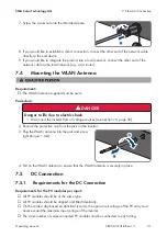
7. Screw the swivel nut onto the threaded sleeve.
1
2
8. If you would like to establish a direct connection, connect the other end of the network cable
directly to the end device.
9. If you would like to integrate the product into a local network, connect the other end of the
network cable to the local network (e.g. via a router).
7.4
Mounting the WLAN Antenna
Requirement:
☐ The WLAN antenna supplied must be used.
Procedure:
1.
DANGER
Danger to life due to electric shock
• Disconnect the inverter from all voltage sources (see Section 10, page 59).
2. Remove the protective cap from the jack on the inverter.
3. Plug the WLAN antenna into the jack and screw
tight (torque: 1 Nm).
1
2
4. Pull on the WLAN antenna to ensure that the WLAN antenna is securely in place.
7.5
DC Connection
7.5.1
Requirements for the DC Connection
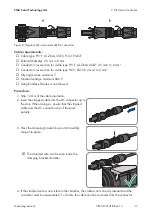
Requirements for the PV modules per input:
☐ All PV modules should be of the same type.
☐ All PV modules should be aligned and tilted identically.
☐ On the coldest day based on statistical records, the open-circuit voltage of the PV array must
never exceed the maximum input voltage of the inverter.
☐ The same number of series-connected PV modules must be connected to each string.


