SMA Solar Technology AG
Installation Guide
SB50US-80US-IUS094030
81
7.4 Measuring Channels and Parameters
The communication options support a number of measuring channels and messages from the Sunny
Boy inverters.
The following abbreviations are used:
The BFR and SRR are redundant processor control systems for the utility protection functions.
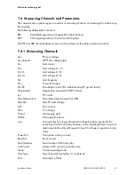
7.4.1 Measuring Channels
BFR
Betriebsführungsrechner (Sequential Control System)
SRR
Stromregelungsrechner (Current Control System)
Vpv:
PV input voltage
Vpv Setpoint:
MPPT DC voltage target
Iac:
Grid current
Vac:
Grid voltage L1 - L2
Vac L1:
Grid voltage L1 - N
Vac L2:
Grid voltage L2 - N
Fac:
Grid frequency
Pac:
Power fed to grid
Vpv-PE:
PV-voltage to earth (For troubleshooting PV ground faults)
Temperature:
Temperature measured at IGBT module
Ipv:
PV current
Max Temperature:
Max temperature measured at IGBT
Max Vpv:
Max PV input voltage
I-dif:
Error current
Vfan:
Fan voltage
E-Total:
Total energy yield
h-Total:
Total operation hours
h-on:
h-on indicates how long sufficient DC voltage has been applied to the
Sunny Boy and the Sunny Boy has been active including the time it was not
able to feed to the utility with respect to low DC voltage or operation in stop
mode.
Power On:
Total system start-up counter
Event-Cnt:
Event counter
Serial Number:
Serial number of the Sunny Boy
CO2 saved:
Amount CO2 saved in operation time
Mode:
Current operating mode
Grid Type:
Type of grid the Sunny Boy is connected to
Error:
Description of fault


