SMA
Technologie AG
Overview
Installation Guide
SB25_30-11:SE0307
Page 11
4 Overview
4.1 Unit Description
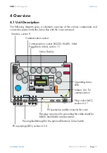
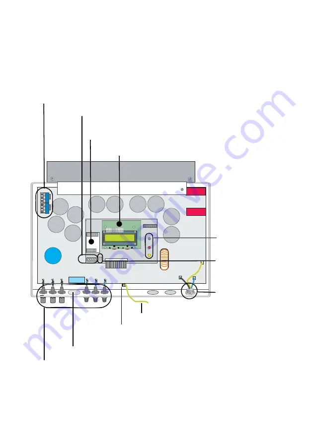
The following diagram gives a schematic overview of the various components and
connection points inside the Sunny Boy with the cover removed:
Varistors, section 9
Communication socket (RS232, RS485, NLM
Piggy-Back, radio), section 11
Sunny Display
Operating status
LEDs
Jumper slot for
communication
Communication socket
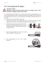
Plug socket (AC),
section 6.2.1
PE (protective earth) connector for cover
Flat plug connection for grounding the cable shield for
RS232 and RS485 communication
PV input plugs (DC), section 6.2.2
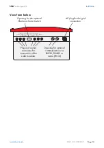
Housing feed-through for the optional Electronic Solar Switch
Summary of Contents for Sunny Boy SB 2500
Page 2: ......
Page 6: ...Explanation of the Symbols Used SMA Technologie AG Page 6 SB25_30 11 SE0307 Installation Guide...
Page 10: ...Safety Instructions SMA Technologie AG Page 10 SB25_30 11 SE0307 Installation Guide...
Page 20: ...Installation Requirements SMA Technologie AG Page 20 SB25_30 11 SE0307 Installation Guide...
Page 62: ...The Communication Interface SMA Technologie AG Page 62 SB25_30 11 SE0307 Installation Guide...
Page 65: ......

