SMA
Technologie AG
Installation Requirements
Installation Guide
SB25_30-11:SE0307
Page 15
5.2 PV Generator Requirements
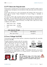
The Sunny Boy is designed to be connected to up to three strings (PV modules wired in
series) having a homogenous structure (modules of the same type, identical orientation
and tilt).
Sunny Design will assist you in the system design and checking of the string size for a
given type of inverter. Further information on Sunny Design is available at
www.SMA.de.
The unit has six DC plug connectors (two for each string) for connecting the PV
generators. The connecting cables from the PV generators must also be fitted with this
type of plug connector. A pre-assembled set for connecting the free cable ends from a
string is available as an optional accessory. The SMA order codes for the various
connectors are as follows:
5.3 Low Voltage Grid (AC)
The Sunny Boy must have a three-conductor connection to the grid (live (L), neutral (N),
protective earth (PE)).
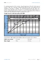
The grid connection terminals on the AC connection
socket included in the accessories kit can take wires
with a cross-section of up to 2.5 mm². The
accessories kit also contains a PG13.5 AC
connection socket for connecting cables with a cross-
section between 9 mm² and 13.5 mm², while the
PG16 connection socket is used for cables with a
cross-section up to a maximum of 17 mm². For detailed instructions, see sections
"Connecting the AC Output with PG13.5" (Page 26) and "Connecting the AC Output
with PG16" (Page 28).
•
Multi-Contact 3 mm:
SWR-MC
•
Multi-Contact 4 mm:
MC-SET
•
Tyco:
TYCO-SET
Limit values for DC input
Max. voltage
600 V (DC)
Max. input current
12 A (DC)
Warning!
We recommend using a 16 A line circuit
breaker to protect the power circuit. No
loads should be connected to this power
circuit.
Cable
diameter
Wire
cross-section
Summary of Contents for Sunny Boy SB 2500
Page 2: ......
Page 6: ...Explanation of the Symbols Used SMA Technologie AG Page 6 SB25_30 11 SE0307 Installation Guide...
Page 10: ...Safety Instructions SMA Technologie AG Page 10 SB25_30 11 SE0307 Installation Guide...
Page 20: ...Installation Requirements SMA Technologie AG Page 20 SB25_30 11 SE0307 Installation Guide...
Page 62: ...The Communication Interface SMA Technologie AG Page 62 SB25_30 11 SE0307 Installation Guide...
Page 65: ......

