SMA
Technologie AG
Rating for a Line Circuit Breaker
Installation Guide
SB25_30-11:SE0307
Page 55
10 Rating for a Line Circuit Breaker
Required Technical Data for the Inverters Used
•
Maximum output current = 12.5 A (Sunny Boy SB 2500)
15 A (Sunny Boy SB 3000)
•
Maximum permissible fuse protection for the inverter = 16 A
The choice of cable together with the way it is routed, ambient temperatures and other
underlying conditions limit the maximum fuse protection for the cable.
•
In our example we assume that the chosen cable (2.5 mm²) is ideally routed and
can take a nominal current of 18.9 A.
Selecting the line circuit breakers:
•
The maximum possible nominal current for the cable used and the maximum
possible fuse protection for the inverter now limit the maximum possible nominal
current for the line circuit breaker.
•
In our example, 16 A is possible.
However, the thermal suitability of the line circuit breaker still needs to be checked.
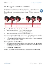
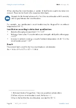
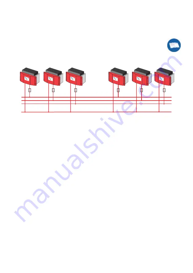
Example for the thermal rating for a line circuit breaker in a photovoltaic power-
generating system operated in parallel with the low voltage grid.
We assume a PV system with 9 Sunny Boy inverters, with three inverters per
phase.
L1
L2
L3
N
...
Betri
eb
Ope
ration
Erdsc
hluss
Earth
Fault
Störun
g
Failure
Photo
voltaik
-String
wechs
elric
hter
Photo
volta
ic strin
g inv
erter
Betrie
b
Operatio
n
Erdschl
uss
Earth
Fault
Störung
Failur
e
Photo
voltaik
-Stringwe
chselrichter
Phot
ovoltaic
string
inverter
Betrieb
Ope
ration
Erds
chlu
ss
Ear
th Fau
lt
Störun
g
Failure
Photo
voltaik
-Strin
gwechs
elric
hter
Photovoltaic
string
invert
er
Betrieb
Op
erati
on
Erdschl
uss
Earth
Fault
Stör
ung
Failure
Photo
volta
ik-Stringwe
chselrichter
Phot
ovolta
ic stri
ng inve
rter
Betr
ieb
Op
eration
Erdschluss
Earth
Fault
Störun
g
Failure
Photo
voltaik
-Stringwe
chselrichter
Phot
ovoltaic
string
inver
ter
Betr
ieb
Op
era
tion
Erdschl
uss
Ear
th Fau
lt
Störun
g
Failure
Pho
tovolt
aik-Stri
ngwechsel
richter
Photo
volta
ic stri
ng inve
rter
Summary of Contents for Sunny Boy SB 2500
Page 2: ......
Page 6: ...Explanation of the Symbols Used SMA Technologie AG Page 6 SB25_30 11 SE0307 Installation Guide...
Page 10: ...Safety Instructions SMA Technologie AG Page 10 SB25_30 11 SE0307 Installation Guide...
Page 20: ...Installation Requirements SMA Technologie AG Page 20 SB25_30 11 SE0307 Installation Guide...
Page 62: ...The Communication Interface SMA Technologie AG Page 62 SB25_30 11 SE0307 Installation Guide...
Page 65: ......

