Technical Data
SMA
Technologie AG
Page 42
SB25_30-11:SE0307
Installation Guide
8.4 Operating Parameters
8.4.1 Explanation of the Operating Parameters
Name
Explanation
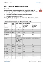
ACVtgRPro
Voltage rise protection (only relevant for Germany).
Sunny Boys can feed into the public grid in Germany with up to
260 V AC. However, DIN VDE 0126-1-1 stipulates that the
average AC voltage over 10 minutes must not exceed 253 V. If
the average over 10 minutes exceeds the threshold value of 253
V, the inverter disconnects itself from the grid. Once the average
over 10 minutes returns to a value of less than 253 V, the inverter
resumes grid feeding. If voltage rise protection is not required in
the relevant grid area (outside Germany), it can be deactivated
by presetting the LDVtgC parameter. In this event, only the fast
cut-off via the Uac-Max parameter intervenes.
AntiIsland-Ampl
Amplification of the AntiIsland process (alternative anti-islanding
process, which is deactivated for Germany).
AntiIsland-Freq
Repetition rate of the AntiIsland process (alternative anti-
islanding process, which is deactivated for Germany).
Betriebsart
Operating mode of the Sunny Boy:
MPP-Betrieb: Maximum Power Point
Konstantspg.: constant voltage mode (nominal voltage is
defined in "Usoll-Konst").
Stop: disconnection from grid, no operation.
Turbine: operating mode for wind turbine systems.
Default
Used for setting country-specific information.
GER/VDE0126-1-1: country-specific parameter settings for
Germany in accordance with DIN VDE 0126-1-1.
SP/RD1663: country-specific parameter settings for Spain.
GB/G83: country-specific parameter settings for Great Britain.
Other: here, parameter settings can be defined for countries for
which no predefined setting exists.
Trimmed: if country-specific parameters have been changed,
"trimmed" is shown on the display.
Off_Grid: settings for inverters which are operated in a stand-
alone grid. More detailed information can be found in the Sunny
Island manual.
Summary of Contents for Sunny Boy SB 2500
Page 2: ......
Page 6: ...Explanation of the Symbols Used SMA Technologie AG Page 6 SB25_30 11 SE0307 Installation Guide...
Page 10: ...Safety Instructions SMA Technologie AG Page 10 SB25_30 11 SE0307 Installation Guide...
Page 20: ...Installation Requirements SMA Technologie AG Page 20 SB25_30 11 SE0307 Installation Guide...
Page 62: ...The Communication Interface SMA Technologie AG Page 62 SB25_30 11 SE0307 Installation Guide...
Page 65: ......


