4-16
SMA America
SB700U-11:SE3207
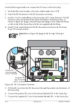
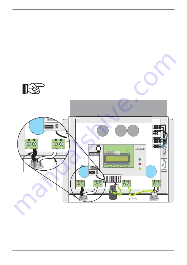
Use the following procedure to connect the DC wires to the Sunny Boy:
1. Verify that the main breaker in the main utility breaker box is OFF.
2. Open the DC disconnect in the DC disconnect enclosure.
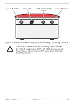
3. Install a ½-inch conduit fitting in the Sunny Boy’s DC wiring knockout. The DC
knockout is the one farthest to the left on the bottom of the Sunny Boy, as
shown in Figure 4-2 (page 4-5) and Figure 4-8 (page 4-16). Fasten the fitting
on the inside of the Sunny Boy with the nut supplied with the fitting.
4. Install ½-inch conduit between the DC disconnect enclosure and the Sunny
Boy’s DC wiring knockout.
Note:
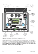
Refer to Figure 4-8 (page 4-16) for steps 5 through
Figure 4-8 DC Connection Terminals
5. Pull the DC wires from the DC disconnect through the conduit into the interior of
the Sunny Boy.
6. Connect the positive DC wire to the terminal labeled DC+ in the Sunny Boy.
7. Connect the negative DC wire to the terminal labeled DC– in the Sunny Boy.
DC–
PE PE
L
N
ENS1 ENS2 S15 S13 S11 S9 S7 S5 200V 150V
2 3 5 7
DC+
DC-–
2 3 5 7
DC+
A
S2
A
B
B
S1
ı ˇ
ˇ
A
S2
A
B
B
S1
Positive DC
wire connected
to DC+ terminal
Negative DC
wire connected
to DC– terminal
Summary of Contents for Sunny Boy SB 700U
Page 1: ...Sunny Boy SB 700U Installation Guide Version 1 1 SB700U 11 SE3207 TBE SB07U...
Page 2: ...ii SMA America SB700U 11 SE3207...
Page 14: ...1 6 SMA America SB700U 11 SE3207...
Page 16: ...2 2 SMA AmericaSB700U 11 SE3207...
Page 24: ...3 8 SMA America SB700U 11 SE3207 11 Verify that the Sunny Boy 700U is firmly mounted in place...
Page 46: ...4 22 SMA America SB700U 11 SE3207...
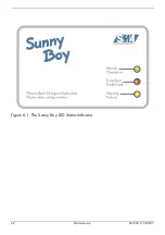
Page 50: ...6 2 SMA America SB700U 11 SE3207 Figure 6 1 The Sunny Boy LED Status Indicator...
Page 84: ...8 6 SMA America SB700U 11 SE3207...
Page 85: ......

