3-4
SMA America
SB700U-11:SE3207
Dimensions and Recommended
Clearances
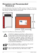
The outer dimensions of the Sunny Boy 700U are shown in Figure 3-2. The Sunny
Boy must be mounted so that there is at least eight inches of clearance above the
heat sink that is mounted on the top of the inverter
Figure 3-2 Outer Dimensions of the Sunny Boy 700U
CAUTION: You
must
ensure that there is sufficient clearance
for heat dissipation above the Sunny Boy’s heat sink! In a nor-
mal operating environment with good ventilation, eight inch-
es of clearance is adequate. However, if the airflow to the
Sunny Boy is restricted or it is subjected to other abnormal op-
erating conditions, enough additional clearance (or forced
ventilation)
must
be provided to allow the heat that the Sunny
Boy produces to dissipate freely.
Note: If additional ventilation is required use the optional
Sunny Breeze fan that mounts to the heat sink.
Note: The National Electrical Code may require significantly
larger working clearances (see NEC Section 110.26).
180 mm
(7.09 in)
320 mm
(12.60 in)
322 mm
(12.68 in)
Summary of Contents for Sunny Boy SB 700U
Page 1: ...Sunny Boy SB 700U Installation Guide Version 1 1 SB700U 11 SE3207 TBE SB07U...
Page 2: ...ii SMA America SB700U 11 SE3207...
Page 14: ...1 6 SMA America SB700U 11 SE3207...
Page 16: ...2 2 SMA AmericaSB700U 11 SE3207...
Page 24: ...3 8 SMA America SB700U 11 SE3207 11 Verify that the Sunny Boy 700U is firmly mounted in place...
Page 46: ...4 22 SMA America SB700U 11 SE3207...
Page 50: ...6 2 SMA America SB700U 11 SE3207 Figure 6 1 The Sunny Boy LED Status Indicator...
Page 84: ...8 6 SMA America SB700U 11 SE3207...
Page 85: ......

