background image

6  Commissioning

SMA Solar Technology AG

System Manual

SBSUL9540-SH-en-10

21

2. Select the configuration option 

Configuration with Installation Assistant

.

☑ The installation assistant will open.

3. Make the network configuration or apply the automatic configuration and select [

Save and

next

].

4. Set the 

Automatic time synchronization

 to [

On

] and in the drop-down list 

Time zone

select the desired time zone.

5. Select [

Save and next

].

6. In the drop-down list 

Set country standard

 select the desired country standard and then

[

Save and next

].

7. In the step 

Meter configuration

, select 

Wattnode Modbus RTU

 from the 

Used energy

meter

 drop-down list.

8. Select [

Save and next

].

9. Grid management service configuration:

• From the drop-down list 

Connected line conductors

, select the line conductor to which

the battery inverter is connected.

• Set 

Feed-in management at the grid-connection point

 to [

Off

].

• Select [

Save and next

].

10. In the step 

Configuration battery/battery-backup system

, check if the connected battery

has been detected and the correct battery type and serial number are listed in the overview

Detected battery types

 and if a green check mark appears in the overview 

Status

.

11. Select [

Save and next

].

12. Check all settings in the summary. You can export the summary or all parameters. Once all

settings are correct, select [

Next

]. The configuration of the Sunny Boy Storage is now

complete.

6.3.4

Setting Time-of-Use (optional)

Time-of-Use

With the "Time-of-Use" function, you can adjust the charging behavior of the battery to your
electricity tariff. Energy bills are thus reduced and electricity at lower cost can be used. You can
determine in which time range the battery with a specified charging power is operated. At specific
times, this is mostly useful when the battery's state of charge has to take on a certain value or the
tariff situation makes the charging more attractive, regardless of the power at the grid-connection
point. The charging parameters set in the power profile are only limited by the state of charge
(SOC). At times when the "Time-of-Use" function is not enabled, the battery is charged
correspondent to the increased self-consumption for the entire system. The "Time-of-Use" function is
disabled by default and must be enabled by creating power profiles.

Procedure:

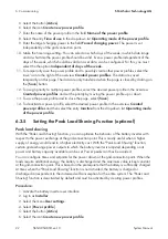
1. Activate the battery inverter user interface.
2. Log in as 

Installer

.

3. Select the menu 

User settings

.

4. Select [

Power profile

].

Summary of Contents for SUNNY BOY STORAGE 3.8-US

Page 1: ...SBSUL9540 SH en 10 Version 1 0 ENGLISH System Manual SMA ENERGY SYSTEM with SUNNY BOY STORAGE 3 8 US 5 0 US 6 0 US...

Page 2: ...ion of implied warranties may not apply in all cases under some statutes and thus the above exclusion may not apply Specifications are subject to change without notice Every attempt has been made to m...

Page 3: ...pairing and using electrical devices batteries and installations Training in the installation and commissioning of electrical devices and installations Knowledge of all applicable laws standards and d...

Page 4: ...of Warning Messages The following levels of warning messages may occur when handling the product DANGER Indicates a hazardous situation which if not avoided will result in death or serious injury WARN...

Page 5: ...inals X703 1 to X703 6 Enter 10 in the field Minutes Connects several elements to be selected Select Settings Date Button Key Button or key to be selected or pressed Select Enter Placeholder for varia...

Page 6: ...ps manuals sma de SB Sxx US 10 en US in dex html Approved batteries and battery commu nication connection Overview of approved batteries and cir cuitry overview of the battery communi cation connectio...

Page 7: ...1 Information on this Document SMA Solar Technology AG System Manual SBSUL9540 SH en 10 7 LG Chem RESU10H www lgchem com BYD BYD B Box H http www eft systems de us...

Page 8: ...cause personal injury or property damage 2 2 IMPORTANT SAFETY INSTRUCTIONS SAVE THESE INSTRUCTIONS This section contains safety information that must be observed at all times when working DANGER Dang...

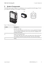
Page 9: ...or damaged B C A Figure 1 Main system components Position Designation A Sunny Boy Storage The Sunny Boy Storage converts the direct current supplied by the battery into grid compliant alternating cur...

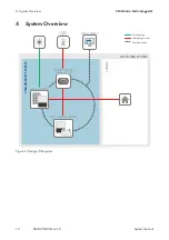
Page 10: ...Manual SBSUL9540 SH en 10 10 4 System Overview SMA ENERGY SYSTEM SUNNY PORTAL CUSTOMER SYSTEM SMA STORAGE SYSTEM UTILITY GRID Alternating current SMA PV SYSTEM Solar energy Communication LOADS ENERGY...

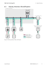
Page 11: ...CHUTZEINRICHTUNG 2x2 2x1 2 2 2 2 2 2 ENERGY METER Modbus RTU Grounding conductor line conductor L1 and L2 Neutral conductor cabel DC 600 V cabel DC 600 V LOADS PV MODULES DISTRIBUTION BOARD GRID CONNE...

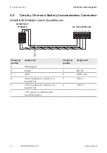
Page 12: ...with LG Chem RESUxxH 1 SUNNY BOY STORAGE 6 5 4 3 2 A B C D E F LG Chem RESUxxH Clamping position Assignment Clamping position Assignment A Not assigned B Enable 3 BAT EN C GND 2 GND AUX D CAN L twist...

Page 13: ...STORAGE A B C D E F 2 4 6 8 10 BYD Battery Box H 1 3 5 7 9 2 4 6 8 10 Clamping position Assignment Clamping position Assignment A Not assigned B Enable 2 EN 11 V C GND 4 EN 11 V D CAN L twisted pair c...

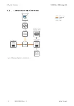
Page 14: ...G System Manual SBSUL9540 SH en 10 14 4 3 Communication Overview SUNNY PORTAL SUNNY BOY SUNNY BOY STORAGE Modbus SWITCH INTERNET ROUTER Ethernet LAN Public Internet CAN BATTERY ENERGY METER Modbus RTU...

Page 15: ...s must not be exposed to direct solar irradiation and must be protected from rain water When becoming too hot the system reduces its power output to avoid overheating The system must not be installed...

Page 16: ...with MAC address binding If DHCP is not supported an IP from the address range of the router must be assigned manually to each device TCP ports 123 443 and 9524 must be authorized for outgoing connect...

Page 17: ...0 22 mm 2 x 2 x 24 AWG Shielding yes Twisted pair conductors UV resistant for outdoor use Maximum cable length 10 m 33 ft Requirements The distribution board is installed The router is installed The s...

Page 18: ...by SMA Solar Technology AG is available at www SMA Solar com 1 Install the battery as specified by the manufacturer 2 Connect the DC conductors the grounding conductor and the communication cable as...

Page 19: ...erter Switch on the AC circuit breaker All three LEDs light up The start up phase begins All three LEDs go out again after approximately 90 seconds Depending on the available power the green LED pulse...

Page 20: ...LAN networks Enter the inverter WLAN password Within the first ten feed in hours and prior to completing the configuration by means of the installation assistant you must use the standard WLAN passwor...

Page 21: ...ery types and if a green check mark appears in the overview Status 11 Select Save and next 12 Check all settings in the summary You can export the summary or all parameters Once all settings are corre...

Page 22: ...o deactivate a power profile select the desired power profile in the overview Created power profiles and then select the entry Inactive from the drop down list Operating mode of the power profile 6 3...

Page 23: ...save the power profile and to possibly create other power profiles select the save icon to the right of the overview Created power profiles The data are saved temporarily on this page The data are onl...

Page 24: ...ight Type and number of PV modules Detailed description of the problem Battery Type Firmware version Sunny Portal System name in Sunny Portal Access data for Sunny Portal United States SMA Solar Techn...

Page 25: ......

Page 26: ...www SMA Solar com...

Reviews: