SMA America, LLC
Operating modes
User Manual
SB_CL_US-BUS094410
13
3 Operating modes
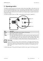
The different operating modes are indicated by 3 light-emitting diodes (LEDs) on the inverter lid, and
also via the integrated display (see section 4 "Information on the display" (page 21)). To allow the
device to signal its operating mode via the 3 integrated LEDs, the inverter must be connected to the
DC side of the system. The level of solar irradiation must be high enough to supply the inverter with
sufficient DC voltage.
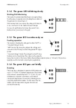
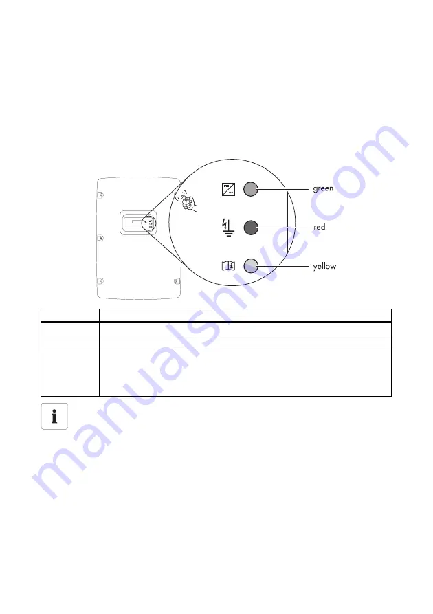
The following diagram shows the 3 LEDs, as exemplified by the Sunny Boy 10000TLUS.
A detailed description of the possible LED signals and blink codes is given in the following section.
LED
Meaning
Green
The green LED indicates normal operation of the inverter.
Red
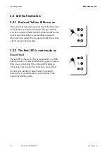
The red LED indicates an earth fault.
Yellow
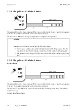
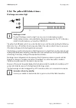
The yellow LED indicates that there is a fault of some kind, either inside the inverter
or somewhere in the PV system. The inverter will not operate until the fault has been
corrected. The different error codes and possible causes are addressed later in this
section and in chapter 6 "Measurement channels and messages" (page 26).
LED Display
If you do not have any means of plant communication, it is advisable, particularly during
the first year of operation, to keep a close eye on this display at different times of day and
under varying solar irradiation conditions. This will enable you to recognize errors at an
early stage.
Summary of Contents for SUNNY BOY US
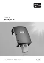
Page 1: ...SB_CL_US BUS094410 TBUS SBUS Version 1 0 US PV Inverter SUNNY BOY US User Manual ...
Page 2: ......
Page 38: ......
Page 39: ......
Page 40: ...4 NFSJDB XXX 4 NFSJDB DPN ...

