background image

Technical Data

SMA Solar Technology AG

76

SSMUS-TUS094511

Technical Description

13 Technical Data

PV generator connection data

1) These values indicate input current without the derating factors of NEC articles 690.8(A)(1) and 690.8(B)(1) applied.
2) These values indicate input current with the derating factors of NEC articles 690.8(A)(1) and 690.8(B)(1) applied.

Sunny Central connection data

Version 24

Version 32

Version 64

Input voltage range

0 ... 600 V DC

0 ... 600 V DC

0 ... 600 V DC

Maximum array system 
voltage (DC)

600 V DC

600 V DC

600 V DC

Maximum operating 
input current per string

20 A 

1)

15 A 

1)

8 A 

1)

Maximum input short 
circuit current (Isc) – per 
string (A DC) 

12.8 A 

2)

9.6 A 

2)

5.1 A 

2)

Maximum input short 
circuit current (Isc) – 
total (A DC)

308 A DC 

2)

308 A DC 

2)

328 A DC 

2)

Maximum fuse rating

20 A

600 V DC

15 A

600 V DC

8 A

600 V DC

Number of input circuits

24

32

64

Fused inputs per 
measuring channel

3

4

8

Configuration PV array

negative or positive 

grounded

negative or positive 

grounded

negative or positive 

grounded

Measuring Channels

8

8

8

Operating 
Consumption

20 W

20 W

20 W

Version 24

Version 32

Version 64

DC short-circuit current

480 A

480 A

512 A

Maximum operating 
output current, 
continous (DC)

308 A

308 A

328 A

Maximum number of 
output lines per 
potential

2

2

2

Summary of Contents for SUNNY CENTRAL STRING-MONITOR US

Page 1: ...SSMUS TUS094511 98 4001411 Version 1 1 US Sunny Central Accessories SUNNY CENTRAL STRING MONITOR US Technical Description...

Page 2: ......

Page 3: ...r its distributors or dealers shall be liable for any indirect incidental or consequential damages under any circumstances The exclusion of implied warranties may not apply in all cases under some sta...

Page 4: ...the Sunny Central String Monitor you must carefully read and follow all instructions cautions and warnings in this Installation Guide Warnings A Warning describes a hazard to equipment or personnel It...

Page 5: ...attention to supplementary information that you should know and use to ensure optimal operation of the system Warning regarding dangerous voltage The product works with high voltages All work on the...

Page 6: ...warnings on the Sunny Central String Monitor the PV array in this Installation Guide and in User Manual PV arrays produce electrical energy when exposed to light and thus can create an electrical shoc...

Page 7: ...of Mounting Location 17 4 1 1 Ambient Conditions 17 4 1 2 Dimensions and Weight 18 4 1 3 Minimum Clearance 18 4 1 4 Permissible Slanting 19 4 1 5 Mounting to PV Module Racks 19 4 2 Mounting to a Pole...

Page 8: ...necting ground 39 7 2 2 Sunny Central Connecting ground 40 7 3 Connecting PV modules negative grounding 41 7 3 1 PV modules Connecting DC 42 7 3 2 PV modules Connecting DC 43 7 4 Connecting the PV mod...

Page 9: ...for Sunny Central String Monitor Controller 66 11 4 2 Parameters for Sunny Central String Monitor 69 11 5 Setting the PV Plant Monitoring System 70 11 6 Optional Settings for the PV plant Monitoring...

Page 10: ...SMA Solar Technology AG 10 SSMUS TUS094511 Technical Description...

Page 11: ...ceived training and has demonstrated skills and knowledge in the construction and operation of the device Qualified personnel is trained to deal with the dangers and hazards involved in installing ele...

Page 12: ...anently measures and monitors the string current of all inputs and detects partial and total dropouts In case of failures and dropouts the responsible person is immediately informed via the WebBox Pri...

Page 13: ...us injuries All work on the Sunny Central String Monitor must only be carried out by a qualified personnel All work on the Sunny Central String Monitor may only be done as described in this manual Pay...

Page 14: ...ched Damage to components Follow ESD protective provisions Remove existing electrostatic charges by touching a grounded metal surface e g housing Storage of the Documentation The documentation must be...

Page 15: ...Contact information for SMA America is provided in chapter 14 Contact page 80 3 2 Packing List Position Description A Sunny Central String Monitor US left version 24 and 32 right version 64 B Install...

Page 16: ...Manufacturing Version Manufacturing version of the Sunny Central String Monitor SMA Solar Technology AG www SMA de SUNNY CENTRAL String Monitor US Model Serial No SSM US 20 107 Fabrication Version P02...

Page 17: ...ocation 4 1 1 Ambient Conditions The installation method and mounting location must be suitable for the weight and dimensions Mounting on a solid surface The mounting location must be accessible at al...

Page 18: ...Central String Monitor may not be mounted to plasterboard walls or similar 4 1 3 Minimum Clearance Keep a clearance of at least 60 in 1 500 mm to walls other devices or similar This clearance is neces...

Page 19: ...ever install the device with a forward tilt Do not install horizontally 4 1 5 Mounting to PV Module Racks The Sunny Central String Monitor can be mounted to the back of module racks It is not permitte...

Page 20: ...nny Central String Monitor accessories kit This section describes mounting to a square pole Two mounting rails are attached to the rear side of the Sunny Central String Monitor In the middle of the mo...

Page 21: ...rection 2 Lift the Sunny Central String Monitor to the mounting position on the pole 3 Slide pole mounts at top and bottom with the closed side to the threaded bolts The required torque is 89 lb in 4...

Page 22: ...rails are attached to the rear side of the Sunny Central String Monitor In the middle of the mounting rails there are 2 internal threads for attaching the pole mount 1 Securely screw the 4 threaded bo...

Page 23: ...ts onto the threaded bolts 6 Tighten the nuts in a clockwise direction with a torque of 89 in lb 7 Shorten the bolts 8 Remove the sharp edges on the bolts using a deburring tool The Sunny Central Stri...

Page 24: ...ody parts possible Ensure that there are studs in the wall at the places where you intend to drill the mounting holes Do not use molly or toggle bolts to mount the Sunny Central String Monitor to shee...

Page 25: ...4511 25 Distance of the holes Used mounting material Attaching to the Sunny Central String Monitor Screws 1 4 stainless steel screws Attaching to the wall Screws 5 16 wood screw length 2 Wall anchor 3...

Page 26: ...Central String Monitor right and left with nuts 1 Loosen the 4 nuts counterclockwise Remove nuts and washers they will be needed later 2 Lay the 4 mounting brackets on the threads of the mounting rai...

Page 27: ...TUS094511 27 8 Insert wall anchors into the drill holes 9 Attach the Sunny Central String Monitor to the wall using screws and washers 10 Tighten the screws clockwise using a torque of 133 in lb 15 Nm...

Page 28: ...tor The right side of the Sunny Central String Monitor can be used for routing the cables 2 Loosen nuts at the metal plates to be used 3 Put the nuts aside 4 Punch holes for the cable conduits into th...

Page 29: ...sible see section 11 2 Communication Overview page 61 The last Sunny Central String Monitor in the bus and the Sunny Central must be terminated see section 6 2 3 Terminate the RS485 bus in the Sunny C...

Page 30: ...are required for the connection Data and Data must be a twisted pair 1 Remove the insulation of the data cable by approx 2 4 in 60 mm and uncover the shield 2 Uncover the wires by approx 1 8 in 45 mm...

Page 31: ...MUS TUS094511 31 6 Tighten the screw terminal using a screwdriver The required torque is 2 2 in lb 0 25 Nm 7 Pull the wires to check that it is securely in place 8 Note down the wire color GND Data Da...

Page 32: ...f the communication bus you only require one socket To ensure sufficient signal quality of the RS485 communication bus it must be terminated on both ends For this connect the termination resistor plug...

Page 33: ...described in section 6 1 Preparing the Data Cable page 30 3 Draw the data cable into the Sunny Central String Monitor see section 5 Attaching the Cable Conduits page 28 4 Connect the plug with one of...

Page 34: ...hten the screw at the shield clamp 4 4 in lb 0 5 Nm 4 Close the Sunny Central String Monitor The data cable is grounded 6 2 3 Terminate the RS485 bus in the Sunny Central String Monitor Only set the t...

Page 35: ...able into the Sunny Central as described in the Sunny Central installation guide 4 Plug the plug to the 485 RJ45 clamp The data cables are attached in the Sunny Central NOTICE Disregarding the proper...

Page 36: ...it back and attach it with conductive adhesive foil 2 Push the two cables portions of shielding reattached in this way into the shielding clamp The shielding of the data cable is grounded SUNNY CENTR...

Page 37: ...1 Connection area NOTICE Electrostatic discharges possible when components are touched Damage to components Follow ESD protective provisions Remove existing electrostatic charges by touching a grounde...

Page 38: ...tor Positive grounding Screw terminals for DC of the PV generator Use 90 C 194 F copper wire for all DC wiring connections to the fuse holders C Negative grounding Screw terminals for DC of the PV gen...

Page 39: ...the cable by approx 0 3 in 8 mm 2 Open the screw terminal with a screwdriver counterclockwise 3 Plug the copper inner conductor of the cable into the screw terminal 4 Tighten the screw terminal with...

Page 40: ...counterclockwise 6 Insert the cable into the Sunny Central String Monitor as described in chapter 5 Attaching the Cable Conduits page 28 7 Plug the copper inner conductor of the cable into the screw...

Page 41: ...Cables of the PV Modules Use 90 C 194 F copper wire for all DC wiring connections to the screw terminals between PV modules and Sunny Central String Monitor Sunny Central String Monitor and Sunny Cen...

Page 42: ...ip the cable by approx 0 3 in 8 mm 2 Open the screw terminal with a screwdriver counterclockwise 3 Plug the copper inner conductor of the cable into the screw terminal 4 Tighten the screw terminal wit...

Page 43: ...12 mm 3 Plug the copper inner conductor of the cable into the fuse holder 4 Tighten the screw in the fuse holder with a screwdriver clockwise The required torque is 19 in lb 2 2 Nm 5 Connect all DC ca...

Page 44: ...e Part II Technical Data for the Connection of the PV Modules Technical Data for the Cables of the PV Modules Use 90 C 194 F copper wire for all DC wiring connections to the Sunny Central String Monit...

Page 45: ...or 1 Strip the cable by approx 0 3 in 8 mm 2 Open the screw terminal with a screwdriver counterclockwise 3 Plug the copper inner conductor of the cable into the screw terminal 4 Tighten the screw term...

Page 46: ...x 0 47 in 12 mm 2 Plug the copper inner conductor of the cable into the fuse holder 3 Tighten the fuse holder with a screwdriver The required torque is 19 in lb 4 Connect all DC cables of the modules...

Page 47: ...Sunny Central Technical Data for the Cables to the Sunny Central Use 90 C 194 F copper wire for all DC wiring connections to the Sunny Central String Monitor DANGER Risk of electric shock through rev...

Page 48: ...wise 6 Insert the cable into the Sunny Central String Monitor as described in chapter 5 Attaching the Cable Conduits page 28 7 Plug the copper inner conductor of the cable into the screw terminal 8 Ti...

Page 49: ...rip the cable by approx 1 1 in 28 mm 2 Open the screw terminal using an Allen key counterclockwise 3 Plug the copper inner conductor of the cable into the screw terminal 4 Tighten the screw terminal u...

Page 50: ...4 Technical Data for the Connection to the Sunny Central Technical Data for the Cables to the Sunny Central Use 90 C 194 F copper wire for all DC wiring connections to the Sunny Central String Monitor...

Page 51: ...wise 6 Insert the cable into the Sunny Central String Monitor as described in chapter 5 Attaching the Cable Conduits page 28 7 Plug the copper inner conductor of the cable into the screw terminal 8 Ti...

Page 52: ...rip the cable by approx 1 1 in 28 mm 2 Open the screw terminal with an Allen key counterclockwise 3 Plug the copper inner conductor of the cable into the screw terminal 4 Tighten the screw terminal us...

Page 53: ...modules with an opaque dark material Follow all safety precautions of the module manufacturer The Sunny Central String Monitor is only one part of the PV power system The commissioning of the Sunny C...

Page 54: ...hem if necessary Check the connectors and insulation for discoloration or degradation Replace any damaged connectors or corroded contacts 12 months Check all string cable connections for looseness and...

Page 55: ...ing Monitor as described in section 10 1 Opening Sunny Central String Monitor page 58 2 Open the fuse holder NOTICE Risk of fire due to incorrectly dimensioned fuse Injuries due to fire For continuous...

Page 56: ...Technical Description 3 Pull the fuse out of the fuse holder 4 Insert the new fuse into the fuse holder 5 Close the fuse holder 6 Close the Sunny Central String Monitor as described in section 10 2 Cl...

Page 57: ...by pulling it forwards 3 Insert the new fuse into the holder 4 Close the Sunny Central String Monitor as described in section 10 2 Closing the Sunny Central String Monitor page 59 The fuse is replace...

Page 58: ...r 3 Open the Sunny Central String Monitor 4 Ensure that no voltage is present in the system 5 Open the fuse holders 6 Pull the fuses out of the fuse holders and lay them aside The Sunny Central String...

Page 59: ...Sunny Central String Monitor 1 Reinsert the fuses into the fuse holders 1 Close the fuse holders 2 Close the Sunny Central String Monitor 3 Commission the Sunny Central as described in the Sunny Centr...

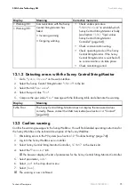
Page 60: ...s Upon leaving our factory the default communication period is set from 10 00 hours 10 00 a m to 15 00 hours 3 00 p m The Sunny Central String Monitors are supplied with energy from the PV panel If fo...

Page 61: ...nitor Technical Description SSMUS TUS094511 61 11 2 Communication Overview Position Description A Sunny Display B Sunny Central Control Unit C Sunny WebBox D Sunny Central String Monitor Controller SC...

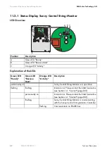
Page 62: ...tivity Green LED Ready Green LED Receive Data Orange LED Activity Description permanently on Sunny Central String Monitor is in operation flashing flashing Internal error Please contact the SMA Servic...

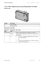
Page 63: ...cription A Green LED RDY B Orange LED ACT Green LED RDY Orange LED ACT Description permanently on Sunny Central String Monitor Controller is in operation flashing Communication is taking place with at...

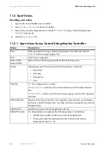
Page 64: ...e of electricity generated by the respective group Mode Operating mode of the Sunny Central String Monitor Controller Operation Warning Disturbance Error ParaCfg Ok The configuration is in order WrnMo...

Page 65: ...fication number of the Sunny Central String Monitor x number of the faulty string current channel 1 to 8 SysDt Current system date Display format mm dd yy mm month dd day yy year SysTm Current system...

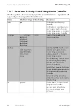
Page 66: ...ComBaud 1200Baud 4800Baud 9600Baud 19200Baud 38400Baud 57600Baud 19200 Speed of data transfer via the communication bus DevFunc AutoDetect_SSMU DetectSSMURetry DelAll_SSMU Factory AutoDetect_SSMU Dele...

Page 67: ...daily communication with the Sunny Central String Monitors stops The time is entered in 24 hour format Hours and minutes are separated by a dot E g for 6 30 p m enter 18 30 MoniTmComOn 6 00 20 00 10...

Page 68: ...This parameter will enable you to set the monitoring end time simultaneously for the parameters MoniTmGr1Off thru MoniTmGr6Off The time is entered in 24 hour format Hours and minutes are separated by...

Page 69: ...Monitor This parameter cannot be adjusted GrCh 0 6 1 This parameter enables you to allocate all the strings connected to the Sunny Central String Monitor to a group GrCh1 GrCh8 0 6 1 Group to which a...

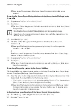
Page 70: ...Do not yet detect the Sunny Central String Monitors 3 Detect the Sunny Central String Monitor Controller and the Sunny Central as described in the instructions to the Sunny WebBox Set the following v...

Page 71: ...oller starts over with the detection of all the Sunny Central String Monitors Detection of the entire system by the Sunny WebBox The Sunny WebBox must detect the entire system i e the Sunny Central th...

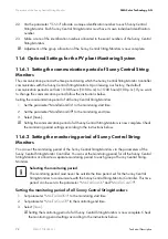
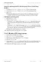
Page 72: ...MoniTmComOn to the monitoring start time 2 Set the parameter MoniTmComOff to the monitoring end time 3 Select Save Setting the communication period of all Sunny Central String Monitors is now complete...

Page 73: ...d of the monitoring period of the particular group is before the beginning of the monitoring period If parameter ParaCfg displays the message WrnMoniTmCom this means that the times for MoniTmComOn or...

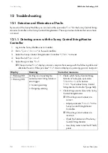
Page 74: ...or If the spot value Error displays an alert compare the message with the following table and eliminate the error If the spot value Error does not display any warning go on to next point Display Meani...

Page 75: ...ller SCSMC in the device list 4 Select the Parameters tab The browser displays the list of parameters for the Sunny Central String Monitor Controller 5 Select parameter Ackn 6 Select quit in the drop...

Page 76: ...Maximum operating input current per string 20 A 1 15 A 1 8 A 1 Maximum input short circuit current Isc per string A DC 12 8 A 2 9 6 A 2 5 1 A 2 Maximum input short circuit current Isc total A DC 308 A...

Page 77: ...800 x 1 200 x 300 Weight 143 lbs 65 kg 146 lbs 66 kg 194 lbs 88 kg Enclosure rating NEMA 3R NEMA 3R NEMA 3R Type of housing Steel or stainless steel Steel or stainless steel Steel or stainless steel A...

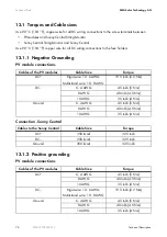
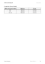
Page 78: ...e grounding PV module connections Cables of the PV modules Cable Size Torque DC Rigid wire 10 6 AWG Multistrand wire 10 8 AWG 19 5 in lb 2 2 Nm DC 6 4 AWG 45 in lb 5 Nm 8 AWG 40 in lb 4 5 Nm 10 AWG 35...

Page 79: ...chnology AG Technical Data Technical Description SSMUS TUS094511 79 Connection Sunny Central Cables to the Sunny Central Cable Size Torque DC 350 kcmil 325 in lb DC 350 kcmil 325 in lb Ground 350 kcmi...

Page 80: ...in order to provide you with the necessary assistance Inverter type Type and number of modules connected Communication method Serial number of the Sunny Central String Monitor Sunny Central failure or...

Page 81: ...SMA Solar Technology AG Contact Technical Description SSMUS TUS094511 81...

Page 82: ...Contact SMA Solar Technology AG 82 SSMUS TUS094511 Technical Description...

Page 83: ......

Page 84: ...SMA America Incorporated XXX TNB BNFSJDB DPN...

Reviews: