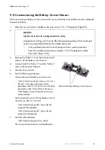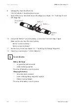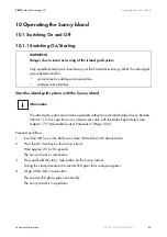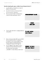
SMA
Solar Technology AG
Operating the Sunny Island
Technical Description
SI2012_2224-TEN082311
95
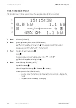
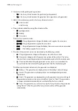
2. Connection to the public grid/a generator:
•
= the Sunny Island monitors the grid limits (grid operation)
•
x
= the Sunny Island monitors the generator limits (operation with generator)
3. MMC/SD card (memory card) in the Sunny Remote Control 1:
•
¿
= card inserted
•
= card missing
4. These indicators label the energy flow direction of the
•
= grid/generator
•
= battery
•
= Consumers
There are four operative states:
•
‡ ‡
= the grid/generator charges the battery and supplies the consumers
•
‡‡‡
= the grid/generator supplies the consumers
•
‡
= the grid/generator charges the battery, there are no consumers connected
•
‡
= the battery supplies the consumers
5. The state of the external sources are described by the following symbols:
•
*
= The grid/generator voltage and frequency are within the set limits
•
?
= Generator voltage and/or frequency are outside of the set limits. The Sunny
Island will not connect the generator to the stand-alone grid while this situation exists.
•
!
= The maximal admissible grid/generator reverse power was exceeded, the
Sunny Island has disconnected the grid/generator from the stand-alone grid.
The following characters indicate why the generator was deployed:
•
B
= Battery = The generator was deployed due to the battery's state of charge.
•
L
= Load = The generator was deployed due to a load-dependent generator
requirement.
•
S
= Start = The generator was deployed due to the operator's manual switching of
the generator activation on the Sunny Island from "Auto" to "Start". The generator is
no longer controlled automatically nor switched off by the Sunny Island.
•
T
= Time = The generator was run for an hour by the Sunny Island via the parameter
setting "Run1h". After this period the Sunny Island switches off the generator
automatically.

