SMA
Solar Technology AG
Sunny Island Electrical Connection
Technical Description
SI2012_2224-TEN082311
43
7.2 DC connection
7.2.1 Grounding
Calculating the Required Grounding Conductor Cross-Section
The SMA Solar Technology AG cannot state generally valid values for the cross-section of the
conductor required for the external grounding of the battery. The conductor dimensions depend on
the type and size of the battery connected, the external fuse (DC side) and the material used for the
grounding conductor.
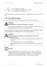
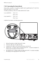
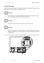
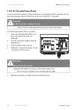
The required cross-section of a (copper) grounding conductor can be calculated using the following
formula. Trigger times, e.g., for the integrated DC circuit breaker and short-circuit currents of
between 2000 and 10,000, are typically about 25 ms.
WARNING!
The Sunny Island 2012 / 2224 has no internal DC fuse.
Install an external DC fuse between the Sunny Island and the battery as a protective
conductor. Dimension the fuse in proportion to the cable cross-section used.
•
Sunny Island 2012: fuse NH01, 250 A (BATFUSE-B.0x)
•
Sunny Island 2224: fuse NH00, 125 A (BATFUSE-A.0x)
External grounding.
•
External grounding of the negative pole of the batteries is possible, because the
batteries and the grid side are galvanically isolated within the Sunny Island. In this
case, make sure that the high currents that may occur under fault conditions can be
adequately diverted.
•
If a connection is required, then this must be made separately, external to the Sunny
Island, by an installer.
•
When grounding the battery, the Sunny Island's enclosure must be additionally
grounded, also in the DC area (see chapter 7.3.1 "Grounding" (Page 47)).
Determining the wire cross-section
Exact calculation of the grounding conductor cross-section must consider the regionally
applicable standards and guidelines (e.g., DIN VDE 0100 Part 540).

