SMA
Solar Technology AG
Sunny Island Electrical Connection
Technical Description
SI2012_2224-TEN082311
47
7.3.1 Grounding
For the ground connection with two redundant protective leads use the PE connections in the AC
connection area of the Sunny Island.
For the ground connection with the protective lead of > 10 mm² use the addtional PE connection
(PE crown on the enclosure) in the DC connection area (see following segment).
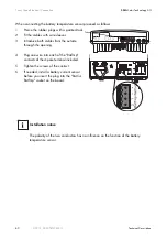
Additional Grounding of the Housing.
If the Sunny Island is used in a country which prescribes the use of a second protective ground (e.g.,
Switzerland), you can ground the enclosure additionally by using the PE crown in the DC
connection area.
Proceed as follows:
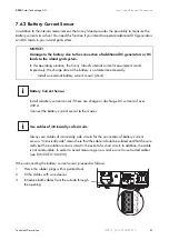
1.
Strip the protective conductor.
2.
Fit the protective conductor with a ringed cable
lug (max. cross-section 50 mm²).
3.
Screw the ringed cable lug onto the enclosure's
PE crown (screw: M8 x 20 mm).
Information
In stand-alone configurations, the (protective) ground of the Sunny Island and its
individual components must be wired as a TN grid only. All valid standards and
guidelines must be taken into account!
CAUTION!
Danger of injury due to leakage current against PE.
The N connection of the Sunny Island has NOT been connected with PE by default.
•
Ground the island grid system outside the Sunny Island before commissioning (see
chapter 7.3.3 "AC2 (Gen/Grid)" (Page 50)).
•
For safety technical reasons (leakage currents of over 3.5 mA),
-
two protective ground wires with 6 mm² (double ground) or
-
one protective ground wire >10 mm².

