SMA
Solar Technology AG
Sunny Island Electrical Connection
Technical Description
SI2012_2224-TEN082311
53
7.5 Communication
7.5.1 Communication with Sunny Island
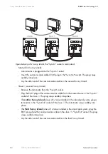
The Sunny Island can be connected in parallel or in a 3-phase system with up to two other Sunny
Islands in order to increase the overall power. The devices communicate through CATe-FTP patch
cables (with two RJ45 plugs each). A patch cable is referred to subsequently as a communication
lead.
Install the communication cable as follows:
1.
Lay the cable equipped with RJ45 plugs through one of the four openings in the inner rubber
element of the cable conduit seal.
Plan a sufficient lead length from the enclosure openings to the desired socket on the
conductor board.
2.
Connect the Sunny Islands as follows:
Notes on the Installation
1.
Lay the communication cable separately from the AC cables.
2.
DO NOT feed the communication leads through the membranes with their plugs
mounted. Feeding the plugs through the membrane would overstretch it, so that
there would no longer be a tight seal around the cable itself, which is thinner.
3.
If the length of the provided communication cables is insufficient, use commercially
available Cat5e FTP cables (single shield) with gold contacts.
4.
The maximum cable length is 30 m. The cable cross-section is at least AWG26/7.
Installation in a Single-Phase, Parallel System or in a 3-Phase System
•
A communication cable is included with each Sunny Island.
You need the cable in order to establish an (internal) communication between
several Sunny Islands. If you operate only one Sunny Island in the cluster the cable
is not required.
•
If needed, choose a parallel/multiphase configuration in the Quick Configuration
Guide (see chapter 9 "(First) Commissioning" (Page 75)).

