5.2.2
Information Page in Systems for Increased Self-Consumption and Battery
Backup Systems
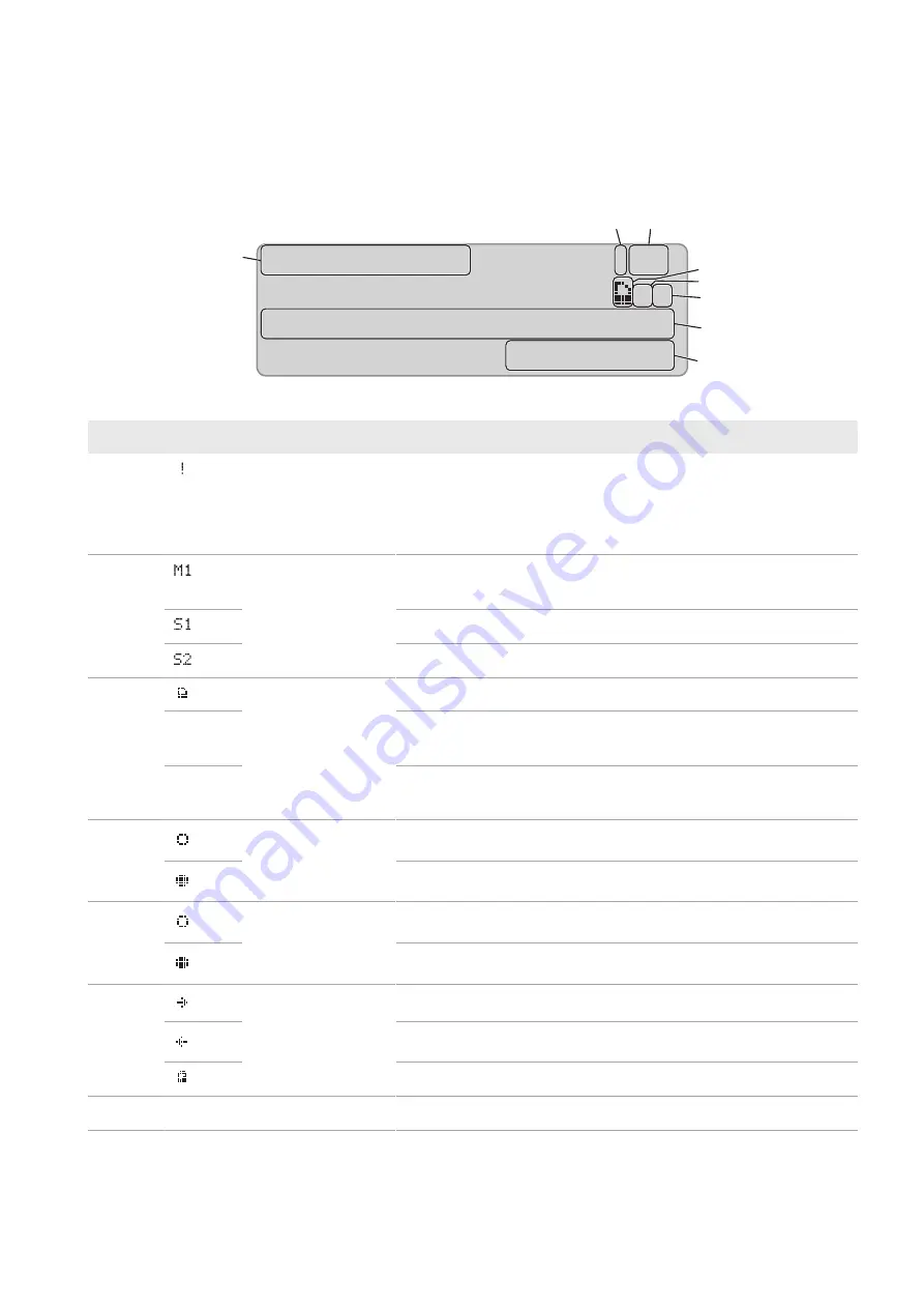
When the Sunny Island is started, the Sunny Remote Control provides information on the status of the system for
increased self-consumption.
H
C
D
F
G
À
1.5kW !M1
oo
!
+-Á 0.0kW SOC 99%
04:17:30
A
B
E
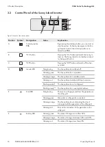
Figure 5: Energy flows and status messages of the Sunny Island
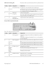
Position
Symbol
Designation
Explanation
A
Warning symbol
Symbol for warnings and errors that do not affect the Sunny Island
operation.
If this symbol is flashing, acknowledge the error or warning (see Sec-
tion 10.3, page 47).
B
Device assignment
The Sunny Island connected to the Sunny Remote Control is the mas-
ter.
The Sunny Island connected to the Sunny Remote Control is slave 1.
The Sunny Island connected to the Sunny Remote Control is slave 2.
C
SD Memory Card
SD memory card is inserted.
Symbol
flashing
The Sunny Island is accessing the SD memory card.
None
Symbol
SD memory card not inserted.
D
Multifunction relay 1
Multifunction relay 1 is deactivated.
Multifunction relay 1 is activated.
E
Multifunction relay 2
Multifunction relay 2 is deactivated.
Multifunction relay 2 is activated.
F
Battery power and
state of charge*
The battery is being charged.
The battery is being discharged.
Battery power in kW, state of charge (SOC) in %
G
hh:mm:ss
Time
System time
5 Operation of the Sunny Island Inverter with the Sunny Remote Control
SMA Solar Technology AG
Operating Manual
25
SI30M-44M-60H-80H-BE-en-33
Summary of Contents for SUNNY ISLAND 3.0M
Page 163: ......
Page 164: ...www SMA Solar com...


