Sunny Island
Installation and Operating Instructions
BWRI45-13:EE0304
- 225 -
SMA Regelsysteme GmbH
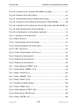
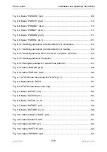
Fig. 3.19: Connection to an „ecopower Mini-BHKW“ and utility ................................. 62
Fig. 3.20: Interfaces of the Sunny Island.................................................................... 64
Fig. 3.21: Recommended cable for RS485 communication....................................... 66
Fig. 3.22: Connection of Sunny Boys at Sunny Island’s COM2 (RS485)................... 68
Fig. 3.23: Connection of Sunny Boys and a Sunny Boy Control at COM2 (RS485) .. 70
Fig. 3.24: Data communication with serial interface................................................... 72
Fig. 3.25: Communication in a three-phase island grid.............................................. 74
Fig. 4.1: Operation of the Sunny Island...................................................................... 75
Fig. 4.2: Menu structure ............................................................................................. 79
Fig. 5.1: Start-up phase of the Sunny Island.............................................................. 81
Fig. 5.2: System message of the Sunny Island.......................................................... 81
Fig. 5.3: “INIT” menu (0-0) ......................................................................................... 82
Fig. 5.4: Status / Menu selection “DATA“ (0-1) .......................................................... 82
Fig. 6.1: Display to enter password............................................................................ 86
Fig. 6.2: Display to enter password............................................................................ 92
Fig. 6.3: Display to enter password............................................................................ 95
Fig. 7.1: Menu selection “OPERAT“ (0-2) .................................................................. 99
Fig. 7.2: Menu branch “OPERAT“ (0-2) ..................................................................... 99
Fig. 7.3: Menu “START“ (2-1) .................................................................................. 100
Fig. 7.4: Menu “GENSET“ (2-2) ............................................................................... 101
Fig. 7.5: Menu “FUNCT“ (2+3) ................................................................................. 104
Fig. 7.6: Update information display......................................................................... 105
Fig. 7.7: Menu „BHKW“ (2+5) .................................................................................. 105
Fig. 8.1: Menu selection “SETUP“ (0-3) ................................................................... 107
Fig. 8.2: Menu branch “SETUP“ (0-3) ...................................................................... 108
Fig. 8.3: Menu “SETTIM“ (3-1) ................................................................................. 108


