Sunny Island 4500
Installation & Operating Instructions
BWRI45-13-EE0304
- 38 -
SMA Regelsysteme GmbH
3.3 Electric Connection
The electric connection of the Sunny Island can be done once the device is correctly
mounted in its position.
The storage battery and the grid (connection to distribution panel) are connected to the
lower part of the Sunny Island. At the bottom of the Sunny Island there are seven
heavy-gauge conduit-threaded joints (four PG 13.5 and three PG16).
3.3.1 Preparing the Connection
Take off the case lid of the inverter’s lower part. To this end remove the two hexagon
socket screws (M5) accessible from the front.
Inside the lid there is a tab and receptacle connector with a green-
yellow grounding cable (PE). Carefully disconnect this connector. After
finishing the installation reconnect it.
Make sure the two automatic circuit breakers F1 and F2 are switched off.
After removing the two fastening screws the lower part of the plastic clamp cover can
be removed as well (“lower protective cover“).
Always mount this “lower protective cover“ again before connecting
any power supply units
.
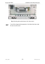
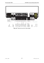
You now have the open part of the inverter in front of you and can familiarize yourself
with the position of relevant components and clamps.


