Sunny Island 4500
Installation & Operating Instructions
BWRI45-13-EE0304
- 50 -
SMA Regelsysteme GmbH
0,1
1
10
100
1
10
100
1000
Distance to current transformer [m]
Po
w
er l
os
s [
W
]
0,75
1,5
2,5
4
6
10
Current Intensity [A] :
Cable material:
Cable cross-
section[mm
2
]
5
=
Copper
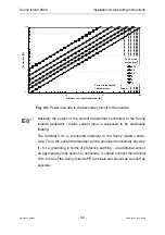
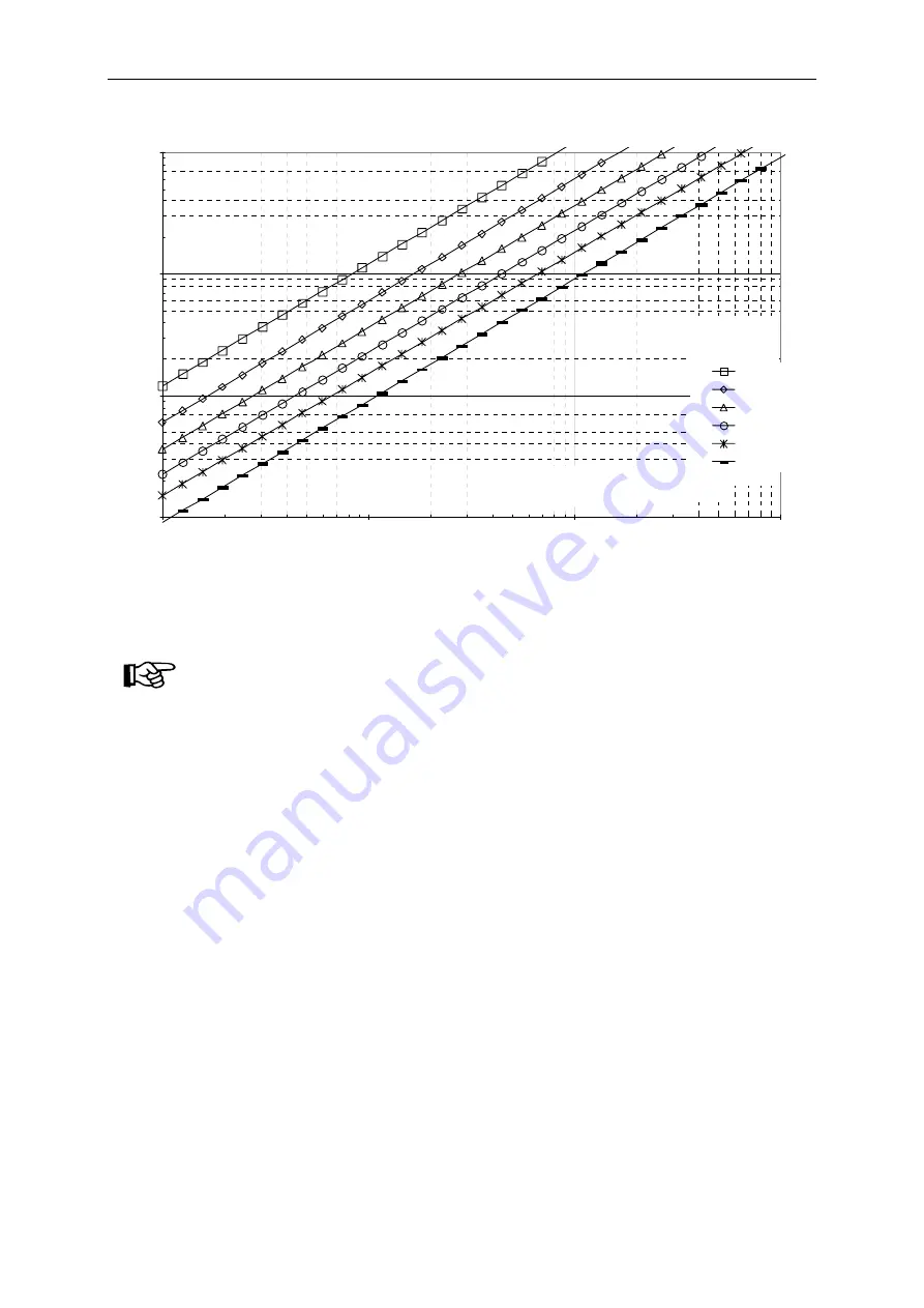
Fig. 3.9:
Power loss due to the secondary circuit to the inverter
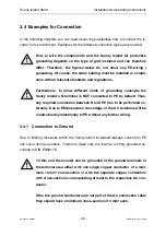
Basically the output of the current transformer connected to the Sunny
Island’s generator / mains current input is supposed to be electrically
floating.
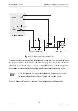
The terminal X2:1 is connected internally to the Sunny Island’s enclo-
sure. Thus, the current transformer will be grounded functionally anyway.
If - for a grounding in terms of protective earthing - an additional wire of
an appropriate cross section is necessary, it should connect the terminal
X2:1 to one of the Sunny Island’s PE terminals and should be as short as
possible.

