Sunny Island 4500
Installation & Operating Instructions
BWRI45-13-EE0304
- 54 -
SMA Regelsysteme GmbH
Sunny Island
13
14
N
L
F2
external distribution
Mains
K3
AC-
Outlet
2 A
L
N
L
N
Grid
L
N
utility grid
SI-
BPRE
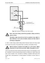
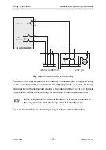
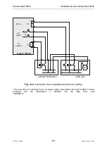
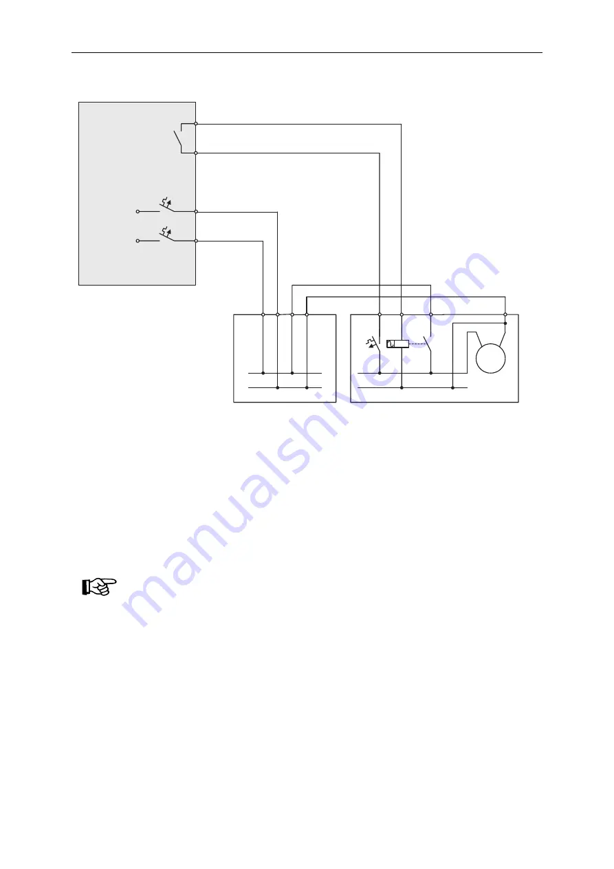
Fig. 3.12:
Connection to an external utility
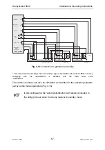
The switch-over times can also be eliminated by means of a more complicated wiring
for the connection to the recovered external utility (Fig. 3.13). Of course, the Sunny
Island can by no means forecast a failure of the external utility. Thus, it is in principle
not possible to reduce this time during the switch-over to island operation mode.
In this configuration the “external distribution” will remain connected to
the utility grid even when the Sunny Island is in standby mode.
Fig. 3.13 does not show the necessary wiring of voltage sensor cables either.


