Sunny Island 4500
Installation & Operating Instructions
BWRI45-13-EE0304
- 58 -
SMA Regelsysteme GmbH
Sunny Island
13
14
13
14
N
L
F2
G
L
N
external distribution
generator
Generator
start
Generator
contactor
K1
K2
generator
start
AC-
outlet
2 A
L
N
PE
L
N
SI-
contactor
K4
24V=
SI-
BP24
2 A
L
N
Grid
L
N
utility grid
13
14
Mains
K3
13
14
K5
L
N
Generator /
Mains
sync. input
Sync switch
*
SI-
BPRE
SI-
BPRE
SI-
BPRE-OE
SI-
BPRE
13
14
+
-
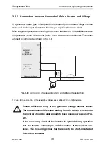
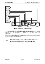
Fig. 3.15:
Example of an accelerated switch-over (generator and utility)
*
This relay shall not overcharge the 24 V auxiliary supply output (SMA order code ”SI-BP24“)! A relay
complying with the requirements is available with the SMA order code
”SI-BPRETR“.
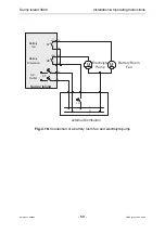
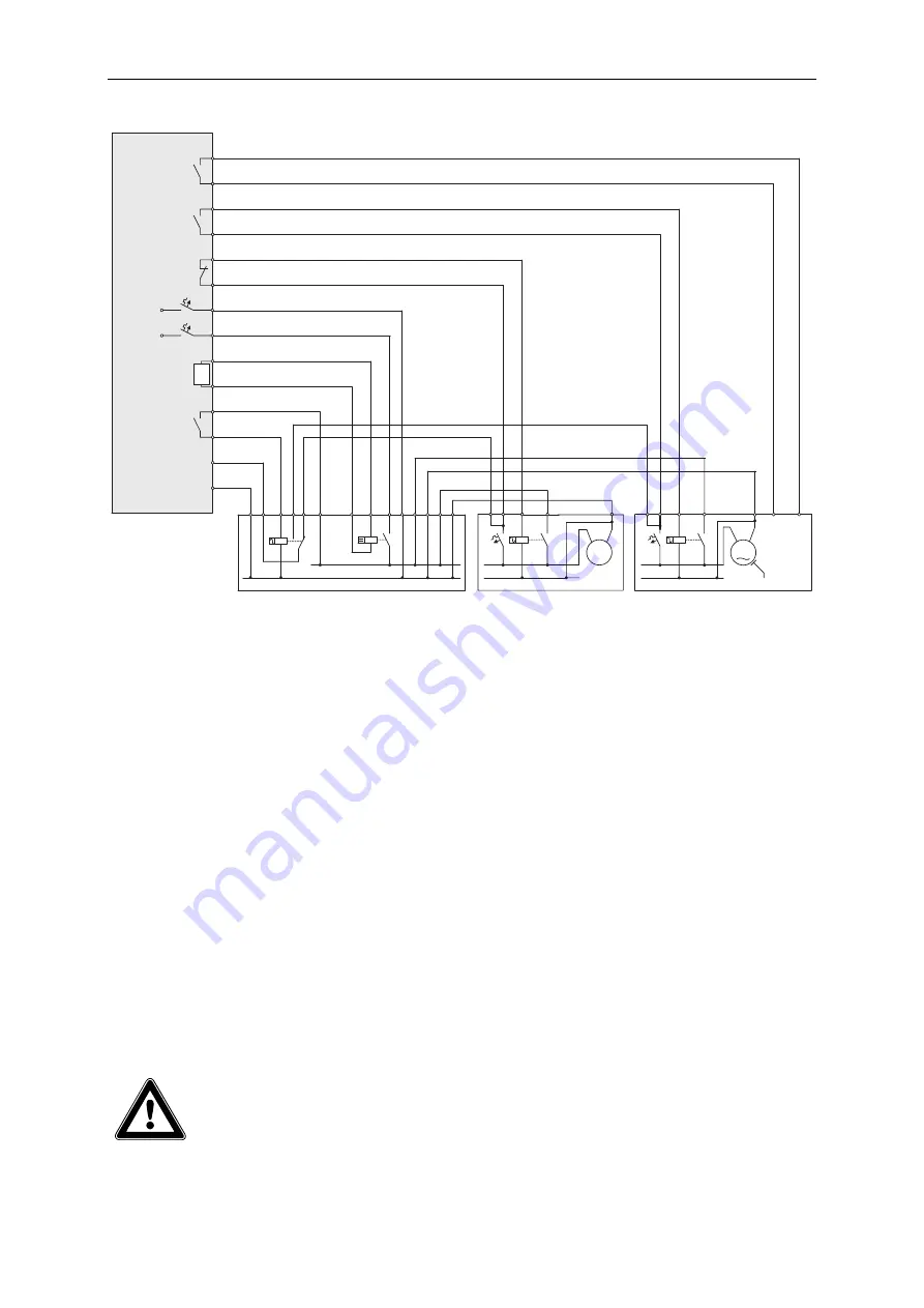
3.4.9 Connection of a Battery Room Fan and Electrolyte Pump
If lead storage battery arrays with liquid electrolytes are used as energy stores, the
control of an electrolyte circulation pump is to be connected via the relay terminal K7.
A battery room fan can be controlled via the relay terminal K8. Switch-on and switch-
off criteria can be defined via the menu of the Sunny Island. For wiring see Fig. 3.16.
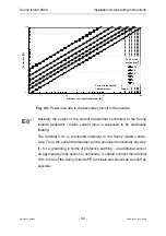
The switched current of the relays K7 and K8 is a maximum of 5 A at
230 V AC. A detailed limit curve is shown in Chapter 13.


