SMA America, LLC
Electrical Connection
Technical Description
SI5048U-TUS121440
47
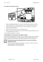
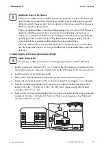
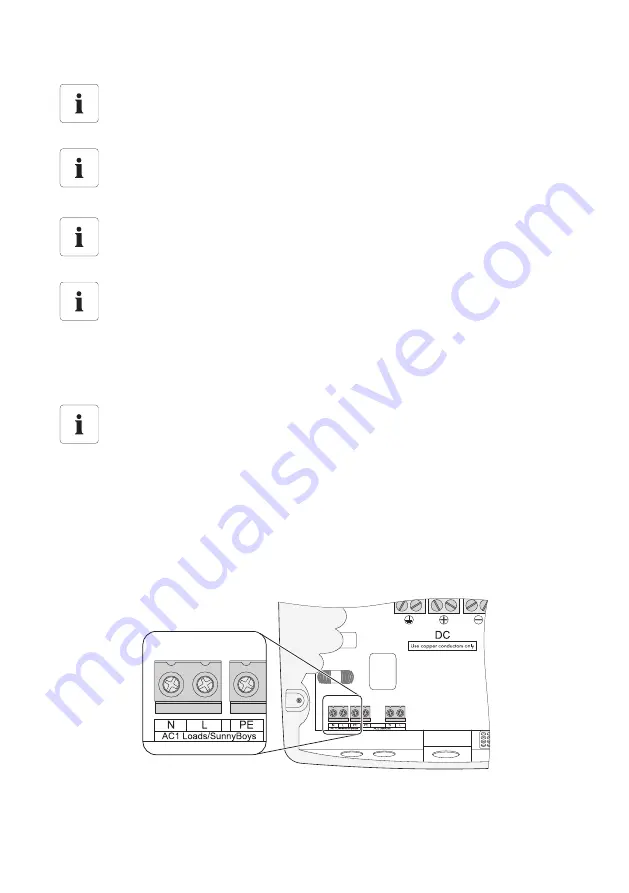
Connecting the AC1 lines:
1. Install a conduit with a diameter of
3
/
4
in. (19 mm) at the left opening on the left side of the
Sunny Island enclosure. Fasten the conduit on the inside of the Sunny Island with a counter nut.
2. Install the conduit on the distribution board.
3. Pull the cable from the distribution board through the conduit into the Sunny Island.
4. Remove the protective insulation of the 3 conductors
(length to be stripped:
3
/
4
in. (18 mm)).
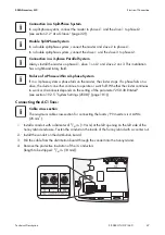
Connection in a Split‑Phase System
In a split‑phase system, connect the master to phase L1 and the slave 1 to phase L2
(see section 2.2 ”At a Glance” (page 22)).
Double Split‑Phase System
In a double split‑phase system, connect the master and slave 2 to phase L1.
In a double split‑phase system, connect the slave 1 and the slave 3 to phase L2.
Connection in a 3‑phase Parallel System
Always install the master on phase L1, slave 1 on L2 and slave 2 on L3. This installation
has a right‑hand rotary field.
Failure of a Phase within a 3‑phase System
If in a 3‑phase system a phase fails on the master, the cluster stops. If a phase fails on a
slave, the cluster can either continue to operate or switch off. Whether the cluster continues
to work or disconnects depends on the setting of the parameter "250.30 RnMod"
(see section 19.2.5 ”System Settings (250#)” (page 181)).
Cable cross‑section
The maximum cable cross‑section for connecting the loads / PV inverters is 4 AWG
(25 mm
2
).

