SMA America, LLC
Electrical Connection
Technical Description
SI5048U-TUS121440
49
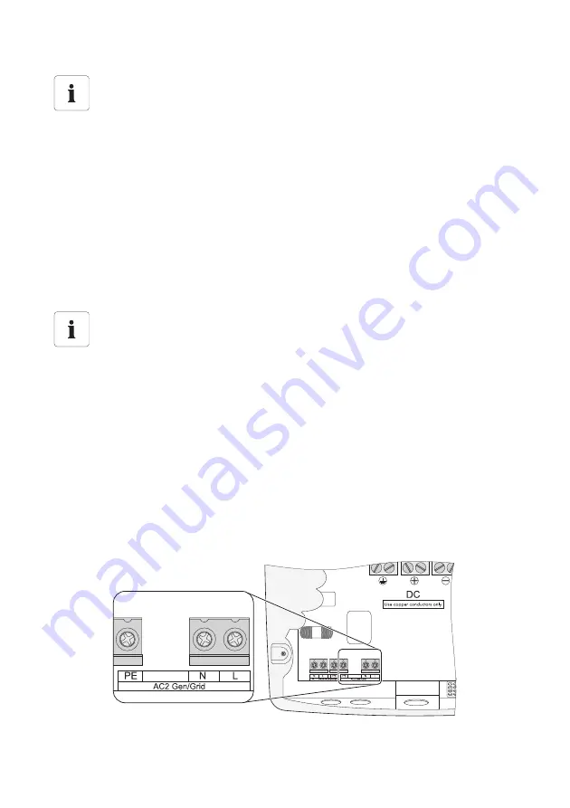
Connecting the AC2 Lines (Generator/Grid):
1. Install a conduit with a diameter of
3
/
4
in. (19 mm) at the right opening on the left side of the
Sunny Island enclosure. Fasten the conduit on the inside of the Sunny Island with a counter nut.
2. Install the conduit on the distribution board.
3. Pull the cable from the distribution board through the conduit into the Sunny Island.
4. Remove the protective insulation of the 3 conductors (length to be stripped:
3
/
4
in. (18 mm)).
5. Insert PE into the terminal labeled "AC2 Gen/Grid" and tighten the fastening screw with a
torque of 22 in-lbs. − 39 in-lbs. (2.5 Nm − 4.5 Nm). Use a torque wrench with flat-head
screwdriver bit SZS 1.0 x 6.5.
6. Insert N and L into the terminals labeled "AC2 Gen/Grid" and tighten the fastening screws with
a torque of 22 in-lbs. − 39 in-lbs. (2.5 Nm − 4.5 Nm). Use a torque wrench with flat-head
screwdriver bit SZS 1.0 x 6.5.
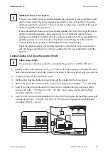
Additional Fuses in the System
If there are no additional fuses installed between the generator or power distribution grid
and the Sunny Island, the Sunny Island knows whether it has a connection to the power
distribution grid/to the generator. The Sunny Island can then draw current from the power
distribution grid/from the generator.
If there are additional fuses or switches installed between the Sunny Island and the power
distribution grid/the generator, the Sunny Island can not determine whether fuses or
switches are separated or whether there is no voltage available from the power distribution
grid/the generator. In either case the Sunny Island cannot charge its battery and the
consumers that are in operation will discharge the Sunny Island battery.
Check the additional fuses and switches regularly in order that the Sunny Island battery
only discharges when there is no voltage available from the power distribution grid/the
generator.
Cable cross‑section
The maximum cable cross‑section for connecting the generator is 4 AWG (25 mm²).


