background image

SMA


Technologie AG

Connecting External Sources

Technical Description

SI5048-11:EE4206

Page 109

14.1.9 Stopping the Sunny Island 5048

If the Sunny Island 5048 is stopped by the user, the generator is immediately
disconnected. The generator is then stopped (generator request, GnReq, is disabled).
The power down phase (Cool) is skipped and the system transitions into the stop time.

14.1.10 Failures

Reverse Power

If the reverse power ("#242.13 GnRvPwr" parameter) set for the "#242.14 GnRvTm"
time is exceeded, the generator is disconnected and stopped. The power down time
(Cool) is skipped and the system transitions into the minimum stop time (Lock). After
reverse power, connection is blocked for at least "#230.02 ExtLkTm" or "#242.09
GnStpTmMin".

Generator Failure

If a generator failure is detected (failure on the master phase), the generator is
disconnected immediately and a stop signal occurs on generator. Afterwards, the
system transitions into the minimum stop time (Lock).

Generator Phase Failure

The failure of a phase (e.g. broken fuse) on a slave device is treated as a phase failure.
The slave device then disconnects this phase. If the phase is detected as being available
again, it is reconnected after the warm up time "#242.12 GnWarmTm" has expired.
The phase failure on the master device is treated as a generator failure (see above).

Slave Device Failure

If a slave device fails, the system continues to operate using both the remaining devices
of the cluster as well as those on the generator.

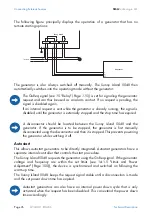
If the generator is started directly at the generator management box or
the generator, it can only be stopped there again. Stopping the Sunny
Island 5048 only disconnects the generator and the system transitions into
the stop time (Lock).

Summary of Contents for Sunny Island 5048

Page 1: ...Sunny Island 5048 Installation Instruction Manual Technical Description Version 1 0 SI5048 11 EE4206 TBE SI5048...

Page 2: ...2 External Total 133 External Slave1 134 External Slave2 135 External Slave3 261 Relay General 262 Relay Load 263 Relay Timer 264 Relay Slave1 265 Relay Slave2 266 Relay Slave3 331 System Device 332 S...

Page 3: ...4 Scope of Delivery 17 2 5 Required Tools and Resources 18 2 6 Accessories Optional 19 2 7 SMA Products Optional 20 2 8 Type Plate Firmware Version 21 3 Safety Instructions 23 3 1 Important Notes Rega...

Page 4: ...erature sensor 41 6 4 2 Battery Current Sensor 42 6 4 3 Communication for Multi device Connection 45 6 4 4 Multi function Relay 1 and 2 47 6 4 5 V_Con Power Supply 49 6 4 6 Digital Input DIGIN 49 6 5...

Page 5: ...0 1 Menu Structure 66 10 2 Changing Parameters 69 10 3 Direct Access 69 10 4 Compact Meters 70 10 5 Entering the Installer Password 72 10 6 Display Messages Overview 73 10 7 Parameter Display 75 10 8...

Page 6: ...8 13 4 1 Boost Charge 90 13 4 2 Full Charge 90 13 4 3 Equalization Charge 90 13 4 4 Manual Equalization Charge 91 13 4 5 Silent Mode 91 13 5 Battery preservation mode 92 13 6 Battery Diagnostics 93 14...

Page 7: ...stment 112 14 2 8 Operation Together With Sunny Boys 113 15 Relay 115 16 Sunny Boy 117 16 1 Connection to the Stand alone Grid 117 16 2 Setting the Stand alone Grid Parameters 118 16 3 Frequency Shift...

Page 8: ...ostart Handling 143 19 4 Master Slave Handling 144 19 5 Handling Pending Errors During the Booting Procedure 144 19 6 Display of Errors and Events 144 19 7 Events 145 19 8 Warnings and Error Messages...

Page 9: ...o not use the Sunny Island 5048 for purposes other than those indicated in this technical description Use of the device for other purposes can void the warranty as well as damage both the device and t...

Page 10: ...1 EE4206 Technical Description 1 3 Syntax The syntax specified here for menus and parameters apply to the entire document Menu hash menu number and menu name 150 Grid Meters Parameter hash menu number...

Page 11: ...isticated generator management it can control connected diesel generators in a particularly sparing and fuel saving manner It can also be integrated into the public grid The Sunny Island 5048 can also...

Page 12: ...n The Sunny Island 5048 also has an integrated anti islanding process that prevents a stand alone grid from accidentally being created on the public grid If this process is triggered the system also c...

Page 13: ...ring inverter Betrieb Operation Erdschluss Earth Fault St rung Failure SWR 3000 Windy Boy Betrieb Operation Erdschluss Earth Fault St rung Failure Betrieb Operation Erdschluss Earth Fault St rung Fail...

Page 14: ...Description ENTER ENTER ESC ESC Island Sunny L1 N PE ENTER ENTER ESC ESC Island Sunny L1 N PE ENTER ENTER ESC ESC Island Sunny Master Slave ENTER ENTER ESC ESC Island Sunny L3 N PE ENTER ENTER ESC ESC...

Page 15: ...Page 15 2 2 At a Glance The following figure provides an overview of all control elements and connections of the Sunny Island 5048 LEDs showing device operation green above Control keys MMC SD card D...

Page 16: ...nd 5048 SMA Technologie AG Page 16 SI5048 11 EE4206 Technical Description 2 3 Dimensions 235 mm 467 mm 612 mm 230 mm Upper edge of the device Upper edge wall bracket Display height 62 mm 700 mm 235 mm...

Page 17: ...ternal communication between several Sunny Island 5048 devices L 1 silicone tube 10 mm x 0 5 m M 1 128 MB SD card N 1 rubber plug for feed through of one cable O 2 rubber plugs for feed through of two...

Page 18: ...le Cable end sleeves Cable knife Combination pliers Crimping tool for cable lugs suitable for cable cross sections of up to 70 mm Diagonal cutting pliers Drill Drill e g stone drill 10 mm Flathead scr...

Page 19: ...arate 48 V DC contactor SMA order number SI LS with 25 40 65 95 A Enables load shedding on the AC or DC side see section 6 4 4 Multi function Relay 1 and 2 Page 47 Separate current shunt for battery c...

Page 20: ...figure on page 13 Sunny Boy inverters for feeding in from PV systems SB 700 SB 1100 SB 1100LV SB 1700 SB 2500 SB 2800i SB 3000 SB 3300 SB 3800 SMC 5000 SMC 5000A SMC 6000 SMC 6000A SMC 6000TL SMC 7000...

Page 21: ...ufacturing date Maximum output power Q de Maximum system voltage 63 V Sunny Island www SMA Technologie AG Hannoversche Stra e 1 5 34266 Niestetal Germany Hotline 49 0 561 9522 399 Utility Interactive...

Page 22: ...The Sunny Island 5048 SMA Technologie AG Page 22 SI5048 11 EE4206 Technical Description...

Page 23: ...nel qualified electrician Never attempt to repair the device yourself Unprofessional repair work can be dangerous Please consult your dealer or SMA Technologie AG if a fault occurs Risk of irreparable...

Page 24: ...the system are completely isolated from all voltage sources battery stand alone grid generator Ensure that the system cannot be accidentally switched on again Proceed in the order given below Switch o...

Page 25: ...a danger of burn injury This device was NOT developed to power life sustaining medical devices The Sunny Island 5048 may not be used in systems where a power outage could result in personal injury Thi...

Page 26: ...Safety Instructions SMA Technologie AG Page 26 SI5048 11 EE4206 Technical Description...

Page 27: ...ing is missing or the Sunny Island 5048 has been damaged during shipment contact SMA Technologie AG immediately For more information please see section 22 Contact Page 159 The Sunny Island 5048 weighs...

Page 28: ...ighs 63 kg Take this weight into account when choosing the installation site and method of installation Protect the Sunny Island 5048 from direct sunlight High temperatures lead to lower performance o...

Page 29: ...to ensure correct alignment Fix the wall bracket using three screws 8 mm diameter The figure below displays the distances of the drill holes in detail for installing the wall bracket The two outer scr...

Page 30: ...holes you can use the wall bracket as a drilling template Now hang the Sunny Island 5048 onto the wall bracket using its mounting plate so that it cannot be moved sideways Secure the Sunny Island 5048...

Page 31: ...ve the six Allen screws 3 Carefully and evenly pull the housing cover until it comes free from the housing 4 Remove the cover and store it in a safe place while mounting installing or repairing the de...

Page 32: ...tools have been removed from within the housing see section 6 Electrical Connection Page 33 1 Starting from the front place the cover evenly on the housing 2 Attach the housing cover onto the Sunny Is...

Page 33: ...ng and also provide strain relief for the cable connection Close all unused openings in the housing using the appropriate dummy plugs the dummy plugs are already installed on AC2 and DC Ground upon de...

Page 34: ...to account Before commissioning the Sunny Island 5048 it must be externally grounded according to the relevant regulations To allow different types of grounding the N connection of the Sunny Island 50...

Page 35: ...ring cable lug to the ground connection terminal and tighten the screw firmly torque 4 0 Nm to 5 7 Nm Calculating the Required Grounding Conductor Cross section SMA Technologie AG cannot calculate gen...

Page 36: ...rding to the maximum specified DC current e g NH1 with 250 A All safety and maintenance instructions provided by the battery manufacturer must be heeded Use appropriate insulated tools for installatio...

Page 37: ...the cable screw connection thread into the cable feed through opening Screw the counter nut onto the cable screw connection thread inside the housing and tighten it 3 Remove the protective insulation...

Page 38: ...sland 5048 If you wish to provide separate protection for an individual load circuit then use maximum 16 A B type circuit breakers In the case of a short circuit the Sunny Island 5048 can still trigge...

Page 39: ...hten it 3 Remove the protective insulation from each of the three wires 4 Install the three wires PE N and L onto AC1 Following the specified sequence insert the appropriate wire into the appropriate...

Page 40: ...screw connection thread into the cable feed through opening Screw the counter nut onto the cable screw connection thread inside the housing and tighten it 3 Remove the protective insulation from each...

Page 41: ...ed battery This is necessary since the optimum charging voltage for a battery strongly depends on the temperature Further information is provided in section 13 4 Charge Control Page 88 A battery tempe...

Page 42: ...ing upper socket 6 4 2 Battery Current Sensor In addition to internally measuring the current the battery current can also be measured using a shunt The current sensor type is set using the 225 01 Bat...

Page 43: ...ble end sleeves through the hole The battery current sensor must be looped around the negative pole of the battery In doing so the side of the shunt that is connected to the Sunny Island 5048 must be...

Page 44: ...l into the corresponding upper socket Make sure to use intrinsically safe cable to connect the battery current sensor Here intrinsically safe means that the cable is double insulated and in the event...

Page 45: ...mon 1 1 computer cable Each Sunny Island 5048 device is delivered with one black and one white RJ45 communication cable You require the black cable to establish internal communication between several...

Page 46: ...et 5 This cable goes into the upper black socket in the next Sunny Island 5048 Any other additional cable would be inserted into the lower socket and lead to the next Sunny Island 5048 there in the up...

Page 47: ...ires with the cable end sleeves in the Relay1 or Relay2 connection terminals of the provided 3 pole print terminals and tighten the screws of these terminals The pins have the following meaning NC Nor...

Page 48: ...erators that can be started and stopped by a single contact and generators that require more than one contact in combination with the optionally available generator manager GenMan Information on the s...

Page 49: ...alling the power supply 1 Pierce a hole in the rubber terminal area at the corresponding position 2 Starting from the outside feed the cable with cable end sleeves through the hole 3 Insert one wire w...

Page 50: ...e cable with cable end sleeves through the hole 3 Insert one wire with the cable end sleeves in each of the DIGIN connection terminals of the provided 4 pole print terminals and tighten the screws of...

Page 51: ...an be found in the communication device manual This wiring diagram includes Details on the required cable type Which of the inverter s connections are used Whether or not the communication cables must...

Page 52: ...s the assignment of the specified pins for the pins of the RJ45 socket 9 Terminate the Sunny Island 5048 at RS485 In the Sunny Island 5048 the RS485 data bus is terminated using a plug This plug is al...

Page 53: ...n structure of your system can be found in the handbook for the communication device you have chosen A Housing feed through in the base of the Sunny Island 5048 B Cable route gray surface C Interface...

Page 54: ...d 5048 GenRq Relay1 AutoGn function see 15 Relay Page 115 GenRn DIGIN For more information on connecting and operating the GenMan please see the corresponding product documentation ENTER ENTER ESC ESC...

Page 55: ...d 5048 has two lines each with 16 characters For details please see section 10 6 Display Messages Overview Page 73 7 2 DC Circuit Breaker The DC circuit breaker is used to switch on off as well as dis...

Page 56: ...eatures an MMC SD card which can be used for updating firmware and as a service interface For details please see section 11 Archiving Data on an MMC SD Card Page 77 Key Functions cancels the selected...

Page 57: ...rect polarity and make sure that everything is connected according to the instructions in section 6 Electrical Connection Page 33 When starting the QCG useful parameter values are set as default setti...

Page 58: ...set when New System is selected Voltage frequency type 230V_50Hz 220V_60Hz default is 230V_50Hz System configuration for this selection see System configuration overview Page 59 default setting is 1ph...

Page 59: ...G 1 phase system 4 Sunny Island 5048 devices offgrid generator 1phase 4SI GB 1 phase system 4 Sunny Island 5048 devices backup on the grid Three 3SI PV 3 phase system 3 Sunny Island 5048 devices photo...

Page 60: ...nged in standby mode see section 9 2 Stopping Page 62 For detailed parameter lists for your system please contact Sunny Island Hotline at the following telephone number 49 561 95 22 399 or by e mail a...

Page 61: ...startup phase Wait for the following displays As soon as the startup phase is finished the message To init system hold Enter is displayed 3 If you would like to access the QCG press and hold Enter un...

Page 62: ...ted If the device unexpectedly displays an error it must be remedied before the device can be operated For this purpose refer to section 19 Troubleshooting Problem Solving Page 143 Note that all conne...

Page 63: ...w the voltage inside the device to drop to a safe level 6 The Sunny Island 5048 is now completely free of voltage and you can open it 9 5 Reactivating the Device Following Automatic Shutdown To reacti...

Page 64: ...the batteries are charged If an autostart generator is present in the stand alone grid the Sunny Island 5048 will request the generator after a few minutes If after reactivation the Sunny Island 5048...

Page 65: ...enu Use ESC to exit the menu and navigate one level higher If you would like to access submenu 7 go backwards starting from 1 and continue past 9 instead of going six steps forwards You can skip menu...

Page 66: ...se is performed at the master 10 1 Menu Structure The menu structure is divided into two levels User level Installer level The menus allowing system parameters to be changed can only be reached after...

Page 67: ...Operation MMC 131 External Device 132 External Total 133 External Slave1 134 External Slave2 135 External Slave3 261 Relay General 262 Relay Load 263 Relay Timer 264 Relay Slave1 265 Relay Slave2 266...

Page 68: ...ers to be viewed and changed Sunny Island 5048 210 Inverter Settings Battery 220 Battery Settings Generator and grid 230 Extern Settings Generator 240 Generator Settings Grid 250 Grid Settings Relay 2...

Page 69: ...ing message for parameters that can only be changed in standby mode or require a different password level 10 3 Direct Access The increment speed of the change increases if you hold the key pressed dow...

Page 70: ...arameter has been set you exit the setting Using ESC you return to Direct Access and you can make additional changes there You can select the different displays of the compact meters using the up down...

Page 71: ...er of inverter cluster Name of the compact meter InvTot 0 5kW 0 0kVAr ExtPwrRt reactive power of ext source ExtFrq frequency of ext source ExtPwrAt effective power of ext source Name of the compact me...

Page 72: ...is information to other persons will lead to invalidation of all SMA Technologie AG guaranty provisions The Sunny Island 5048 also allows the password to be entered while in standby mode 1 You are in...

Page 73: ...y and for load side loads Sunny Boys The arrows between the symbols indicate the direction of energy flow The device assignment follows master or slave e g M1 or S1 Next to this assignment the status...

Page 74: ...ime has passed the Sunny Island 5048 automatically switches off the generator The messages for both relays filled in circle activated open circle deactivated follows in the lower line The line ends wi...

Page 75: ...or charging power and in the lower line the device assignment e g S1 for slave 1 and where applicable the status of external sources for a description please see further above are displayed In the up...

Page 76: ...ing or the fault occurred C on the right in the upper line indicates when the warning or the error was confirmed or cleared The serial number quantity of the events the time and date display which cha...

Page 77: ...he Sunny Island 5048 uses the MMC SD card for saving and loading device parameters In addition the Sunny Island 5048 supports the acquisition and archiving of measuring data on the MMC SD card It save...

Page 78: ...essed using common table calculation programs The first 14 lines of the file are used for information file header and then two column heading lines follow The following data is separated by a semicolo...

Page 79: ...he card The initialization of the MMC SD card can take several minutes During this time the keys are disabled and cannot be used for making entries Three points appear in the lower line of the display...

Page 80: ...ed by the Sunny Island 5048 Please note this when writing data to your card If the Sunny Island 5048 is writing data to the MMC SD card removing the card is prohibited and the following message appear...

Page 81: ...version it transmits its firmware to the slave and makes sure that all Sunny Island 5048 devices within a system operate with the identical firmware version For help on troubleshooting refer to secti...

Page 82: ...ogie AG Page 82 SI5048 11 EE4206 Technical Description Following a successful update the slaves must be manually started once even when the 270 01 AutoStr parameter is set Individual parameters and se...

Page 83: ...ate and time 12 3 Overload and Short circuit Behavior The Sunny Island 5048 can be temporarily operated under overload conditions It can also supply short circuit currents In case of overload the Sunn...

Page 84: ...ustment AFRA function of the Sunny Island 5048 also referred to as a tertiary control allows the trouble free use of grid connected clocks in these types of stand alone systems This function is activa...

Page 85: ...l battery voltage 221 03 BatVtgNom parameter of 48 V 24 cells for every 2 V with lead acid batteries FLA and VRLA and 45 6 V 38 cells for every 1 2 V with nickel cadmium batteries 13 1 Battery Tempera...

Page 86: ...ge Since fully charged states are only rarely achieved in specific offgrid applications the operation used here can also utilize the battery voltage during constant discharge phases with low discharge...

Page 87: ...permanent or only a temporary basis The battery s state of health display value 342 01 Soh is a percentage measurement for the current useable capacity relative to the nominal capacity 100 means that...

Page 88: ...constant voltage charging absorption phase begins In this phase the battery voltage is maintained at a constant level resulting in a continually decreasing battery current The Sunny Island 5048 remai...

Page 89: ...For temperatures 20 C the charging voltage must be slightly increased and for temperatures 20 C it must be slightly decreased This is necessary to reliably prevent overcharging and insufficient charg...

Page 90: ...tly differently Over time this results in different charge levels in the individual cells This can lead to premature failure initially of individual cells and finally to failure of the entire bank The...

Page 91: ...y voltage per cell is 0 14 V lower than the set voltage 222 10 ChrgVtgFlo parameter This ensures that the battery is always fully charged even in silent mode If a grid dropout is detected during silen...

Page 92: ...the stop time using the 223 02 BatPro1TmStp parameter Level 2 The second level of the battery preservation mode ensures that the inverter regularly starts every two hours but only during the window of...

Page 93: ...e it switches off again 13 6 Battery Diagnostics In the menu 342 Statistic Battery many values are displayed that provide information on the past operational behavior of the battery These values are h...

Page 94: ...Battery Management SMA Technologie AG Page 94 SI5048 11 EE4206 Technical Description...

Page 95: ...ng modes to be used without making additional adjustments 14 1 Generator Depending on the battery charge state or the consumer power the Sunny Island 5048 can start a generator and of course stop it a...

Page 96: ...and 5048 keeps the request signal stable until a disconnection is made and the set power down time has expired The GnReq signal see 15 Relay Page 115 is set for signaling the generator request and can...

Page 97: ...Req signal the Sunny Island 5048 requests the generator at the GenMan and keeps this signal stable until the request is successful The GenMan returns the GENRDY signal via DIGIN see 6 6 GenMan Connect...

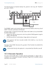
Page 98: ...tery charge state are also ignored The Sunny Island 5048 disconnects the generator if the GenMan has disabled the GENRDY signal 14 1 2 Generator Operation The Sunny Island 5048 allows automatic operat...

Page 99: ...is manually started Cancels the current generator request immediately disconnects from the generator and transitions into the lockout state Once the lockout time has ended the generator switches into...

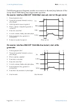
Page 100: ...ator request is ignored 4 Warm up phase is completed generator is connected 5 Generator current limit 6 Current is reduced battery absorption phase 7 Manual generator stop generator is disconnected 8...

Page 101: ...the start time for t2 end of t1 is defined using GnTm2Str 1 Generator start at GenMan 2 GenMan generator warm up phase begins 3 Generator warm up time 4 GenMan sends ready for connection signal 5 Sunn...

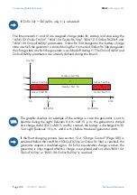
Page 102: ...The graphic displays an example of the settings in case the generator is not to operate during the night Between 6 a m and 10 p m the generator is started at a charge state SOC of 40 and by contrast...

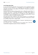
Page 103: ...eters The average time by which an average value for the consumer power is calculated can be set using 241 12 GnPwrAvgTm This prevents temporary power consumption peaks that last for several seconds f...

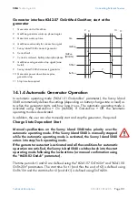
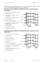
Page 104: ...6 Minimum run time has expired 7 Current is reduced battery absorption phase 8 Charging process is completed request signal is disabled 9 Manual generator stop 10 Generator is disconnected 11 Minimum...

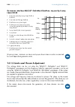
Page 105: ...nnect the generator If the limits are not maintained slave devices where applicable connect or disconnect individually 1 Generator started by Sunny Island 5048 at GenMan 2 Generator start through GenM...

Page 106: ...determines the partitioning of the reactive power between the Sunny Island 5048 and generator or grid In the external setting default an attempt is made to provide the full reactive power through the...

Page 107: ...eded the system transitions into the locked error state This state lasts for the 242 11 GnErrStpTm time Once this time has expired the generator is ready for another attempt The 140 03 GnRmgTm process...

Page 108: ...e synchronization until the AC feed in generators Sunny Boys are disconnected from the stand alone grid as a result of the grid limits being exceeded 14 1 8 Stopping the Generator If the Sunny Island...

Page 109: ...tor failure is detected failure on the master phase the generator is disconnected immediately and a stop signal occurs on generator Afterwards the system transitions into the minimum stop time Lock Ge...

Page 110: ...nerator operation The limits are therefore set separately for grid operation and the generator limits are not used 14 2 2 Starting the Sunny Island 5048 The Sunny Island 5048 always starts in stand al...

Page 111: ...tion the grid monitors whether the permissible limits for voltage and frequency see Grid Reconnection are maintained or whether the grid fails to assume powering the stand alone grid To do this the ma...

Page 112: ...InvChrgCurMax parameter on the Sunny Island 5048 and the DC charging current limit 222 01 BatChrgCurMax parameter are active at the same time If the battery voltage reaches the charging voltage nomina...

Page 113: ...econnected the frequency would be lowered if required as the Sunny Island 5048 is synchronized with the grid The AC feed in generators Sunny Boys would then feed additional energy into the system and...

Page 114: ...Connecting External Sources SMA Technologie AG Page 114 SI5048 11 EE4206 Technical Description...

Page 115: ...e g generator AutoLodSoc Auto LoadShedding Soc automatic load disconnection load is only connected if SOC has exceeded the set value again Tm1 Timer 1 programmable timer once daily weekly with duty c...

Page 116: ...tact functions in other words the contact is closed if the relay is activated by selecting the function For the exception Alm the relay has a break function This means that the relay is normally activ...

Page 117: ...6 1 Connection to the Stand alone Grid Connect the Sunny Boy inverter to the grid in accordance with the Sunny Boy installation guide Wire the AC sub distribution unit to the AC1 terminals of the Sunn...

Page 118: ...ements of DIN VDE 0126 1 1 Observe all regionally relevant regulations and discuss this with the local electricity supply company responsible For changing the grid relevant parameters in the Sunny Boy...

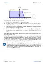
Page 119: ...he value specified by Fac Start delta the Sunny Boy limits its output power accordingly This function is shown in the following figure 3 Uac Max V 260 4 Fac delta lower range in which the Sunny Boy is...

Page 120: ...the grid When FSPC is activated and the diesel generator in the stand alone grid is operating the diesel generator determines the frequency and the Sunny Boys react to certain changes in the diesel ge...

Page 121: ...lean them with the aid of a vacuum cleaner recommended or a soft brush Clean the fans only when at a standstill If it is necessary to replace the fans please contact your installer 17 3 Display It is...

Page 122: ...nce and Care SMA Technologie AG Page 122 SI5048 11 EE4206 Technical Description 17 5 Battery A battery must be checked and maintained regularly In this regard observe the battery manufacturer s specif...

Page 123: ...Battery Operation 430 Operation Generator 440 Operation MMC 131 External Device 132 External Total 133 External Slave1 134 External Slave2 135 External Slave3 261 Relay General 262 Relay Load 263 Rel...

Page 124: ...of all parameters that you change The current parameter settings can be saved onto the MMC SD card using the 410 02 ParaSto parameter This is especially useful if you wish to try out new settings Once...

Page 125: ...1 V inverter voltage on slave 1 113 04 InvCurSlv1 A inverter current on slave 1 113 05 InvPwrRtSlv1 kVAr reactive power of inverter on slave 1 113 06 Rly1SttSlv1 Off On state of relay 1 on slave 1 113...

Page 126: ...attery voltage 120 03 BatChrgVtg V nominal value of charging voltage 120 04 AptTmRmg hhmmss remaining absorption time 120 05 BatChrgOp Boost Full Equalize Float Silent Active charging process boost ch...

Page 127: ...e 133 External Slave1 133 01 ExtPwrAtSlv1 kW effective power of external source on slave 1 133 02 ExtVtgSlv1 V voltage of external source on slave 1 133 03 ExtCurSlv1 A current of external source on s...

Page 128: ...Connect Run Retry Disconnect Cool Lock Fail FailLock Generator state switched off waiting for request ready warming up connecting operation restarting disconnecting cooling down locked after operatio...

Page 129: ...ebBox or a Sunny Boy Control see section 6 5 Interface for External Communication Page 51 Menu no Para meter no Parameter name Range Short descr Value Description 210 01 InvVtgNom V 230 nominal invert...

Page 130: ...ion charge 10 VRLA 10 FLA 10 NiCd depending on the setting in QCG 222 05 CycTmFul d 14 full charge cycle time 222 06 CycTmEqu d 180 equalization charge cycle time 222 07 ChrgVtgBoost V 2 4 cell voltag...

Page 131: ...ervation mode level 1 223 06 BatPro2Soc 15 SOC limit for preservation mode level 2 223 07 BatPro3Soc 10 SOC limit for preservation mode level 3 224 Battery Silent Mode 224 01 SilentEna Disable Enable...

Page 132: ...Description 241 Start Settings 241 01 GnAutoEna Off On On activate generator autostart 241 02 GnAutoStr 3 number of autostarts 241 03 GnSocTm1Str 40 SOC limit for switching on generator for time 1 241...

Page 133: ...Hz 60 maximum generator frequency 60 230V_50HZ 70 220V_60HZ depending on the setting in QCG 242 07 GnStrMod Stby Manual Autostart GenMan Autostart generator interface 242 08 GnOpTmMin min 15 minimum...

Page 134: ...0 220V_60HZ depending on the setting in QCG 250 05 GdFrqMin Hz 47 5 minimum grid frequency 47 5 230V_50HZ 59 3 220V_60HZ depending on the setting in QCG 250 06 GdFrqMax Hz 50 2 maximum grid frequency...

Page 135: ...tion currently has no function currently has no function battery room fan electrolyte pump 261 02 Rly2Op see 261 01 AutoLodSoc Function of relay 2 for details see 261 01 262 Relay Load 262 01 LodSocTm...

Page 136: ...nction of relay 1 on slave 2 for details see 261 01 265 02 Rly2OpSlv2 see 261 01 Off Function of relay 2 on slave 2 for details see 261 01 266 Relay Slave3 266 01 Rly1OpSlv3 see 261 01 Off Function of...

Page 137: ...e 137 270 08 TertCtlEna Stby Disable Enable Enable activation of tertiary control AFRA The 280 Password Setting menu is described in detail in section 10 5 Entering the Installer Password Page 72 Menu...

Page 138: ...tCfgAt 1Phase1 1Phase2 1Phase3 1Phase4 3Phase set cluster configuration depending on the setting in QCG 331 06 OpStt Operating Warning Failure operating mode device 331 07 CardStt Off Operational Moun...

Page 139: ...L1 L2 L3 phase position on slave 2 333 05 OpSttSlv2 Operating Warning Failure operating mode slave 2 333 06 FwVer2Slv2 DSP firmware version 333 07 FwVer3Slv2 BFR boot loader on slave 2 333 08 FwVer4Sl...

Page 140: ...g ampere hours 342 08 BatTmpPkMin degC minimum battery temperature 342 09 BatTmpPkMax degC maximum battery temperature 342 10 EquChrgCnt equalization charge meter 342 11 FulChrgCnt full charge meter 3...

Page 141: ...r operation 410 04 InvTmOpStrDt yyyymmdd 20060101 start date of time controlled inverter operation 410 05 InvTmOpStrTm hhmmss 0 start time of time controlled inverter operation 410 06 InvTmOpRnDur hhm...

Page 142: ...escription 430 01 GnManStr Auto Stop Start Run1h ManEquChrg Auto manual generator start 430 02 GnAck Ackn error confirmation for generator fault Menu no Para meter no Name Range Short descr Default De...

Page 143: ...Sunny Island 5048 runs uninterrupted for over 10 minutes the autostart meter is reset to its initial value If another fault occurs when the autostart meter is at 0 the Sunny Island 5048 waits for 10...

Page 144: ...ay an error that is still pending after the booting procedure is re entered or if the system detects that this error has stopped it is entered as no longer being present 19 6 Display of Errors and Eve...

Page 145: ...rid operation at external input E107 sleep mode slave in 1 phase systems E108 silent mode on the grid E110 shutting down due to fault E115 emergency charge E118 automatic start E119 manual start trans...

Page 146: ...on E603 relay 1 on slave 1 off E604 relay 1 on slave 1 on E605 relay 1 on slave 2 off E606 relay 1 on slave 2 on E607 relay 1 on slave 3 off E608 relay 1 on slave 3 on E609 transfer relay open E610 t...

Page 147: ...mperature on heatsink on slave 3 F117 2 AC current limit short circuit control active for too long F118 2 AC current limit short circuit control active for too long on slave 1 F119 2 AC current limit...

Page 148: ...cessive external voltage F320 1 grid generator disconnection due to excessive external voltage on slave 1 F321 1 grid generator disconnection due to excessive external voltage on slave 2 F322 1 grid g...

Page 149: ...several times in succession F708 4 watchdog meter on slave 2 has expired watchdog triggered several times in succession F709 4 watchdog meter on slave 3 has expired watchdog triggered several times in...

Page 150: ...on on restarting the Sunny Island 5048 see section 9 5 Reactivating the Device Following Automatic Shutdown Page 63 F736 3 no message from cluster on slave 3 F738 1 synchronization not successful F739...

Page 151: ...generator are too strict parameter in menu 242 General Settings Change voltage and or frequency limits according to the technical data of your generator Why is the stand alone grid frequency not at 50...

Page 152: ...the voltage and frequency values The fuses on the generator may have been triggered What do I have to do if the Sunny Island 5048 continuously goes out after Low Battery Mode LBM when restarting the...

Page 153: ...ibed below If AC1 and AC2 have been bridged the generator should first be connected and then started manually Otherwise the magnetizing current could throw the generator fuse This can also happen when...

Page 154: ...rgency charge mode ECM 8 Press ENTER to stop the Sunny Island 5048 The following message appears 9 Hold ENTER pressed down and the remaining time is shown using bars on the display 10 The emergency ch...

Page 155: ...C nom 21 A Max current peak value for 100 ms 100 A 100 ms Harmonic distortion of output voltage KVAC 3 Power factor cos 1 to 1 Input data Input voltage VAC ext adjustable 230 V 172 5 to 250 V Input fr...

Page 156: ...in charge mode DIN EN 61000 6 1 DIN EN 61000 6 2 DIN EN 61000 6 3 DIN EN 61000 6 4 Certification CE Protection degree According to DIN EN 60529 IP 40 with MMC SD card plugs otherwise IP 30 Device prot...

Page 157: ...9 V up to 63 V low level 0 3 V Load limits for multi function relays 1 and 2 AC 1 A at 250 V DC see graphic Mechanical data Width x height x depth 467 x 612 x 235 mm Weight approx 63 kg Ambient condi...

Page 158: ...12 DIN EN 61000 6 1 2002 08 DIN EN 61000 6 2 2002 08 DIN EN 61000 6 3 2002 08 DIN EN 61000 6 4 2002 08 The above mentioned device is therefore marked with a CE sign Note This declaration of conformity...

Page 159: ...ial number see type plate or parameter 331 03 SN Firmware version see parameter 331 02 FwVer Error message shown on the display Battery type Nominal battery capacity Nominal battery voltage Communicat...

Page 160: ...Contact SMA Technologie AG Page 160 SI5048 11 EE4206 Technical Description...

Page 161: ...They usually have very good high current properties but are not very charge cycle resistant Ah Abbreviation for Ampere hours Unit of electrical charge one ampere hour is the charge provided by a const...

Page 162: ...charging the batteries Battery system Serial and possibly also parallel connection of several identical batteries Battery banks of 12 V 24 V 48 V and 60 V are typical Boost charge Rapid charging Allow...

Page 163: ...used instead of performing a complete shutdown of the system DSP Abbreviation for Digital Signal Processor A DSP is a microprocessor chip especially developed for digital signal processing and contro...

Page 164: ...a level of approx 95 on a regular basis at least once a month This efficiently avoids premature aging of the batteries caused by inadequate charging Gel battery A type of battery in which the electrol...

Page 165: ...imum Power Point MPP The working point current voltage characteristic curve of a PV generator where the maximum power can be drawn The actual MMP changes constantly depending e g on the level of solar...

Page 166: ...increase performance or expand capabilities A piggy back board can also replace a single chip In this case the chip is removed and the board is plugged into the empty socket PLC Abbreviation for Powe...

Page 167: ...trical connection of several solar cells encapsulated in a housing to protect the sen sitive cells from mechanical stress and environmental effects Solar cell An electronic component that generates el...

Page 168: ...is connected to the external mains supply with its own string inverter This greatly simplifies installation and greatly reduces the yield losses caused by manufacturing deviations or variations in sha...

Page 169: ...SMA Technologie AG Glossary Technical Description SI5048 11 EE4206 Seite 169...

Page 170: ...protection conditions Altering the product or supplied software without authority The product malfunctions due to operating attached or neighboring devices beyond statutory limit values In case of unf...

Page 171: ......
Page 172: ...Innovation in Systems Technology for the Success of Photovoltaics SMA Ib rica Tecnolog a Solar S L Barcelona Spain E mail info SMA Iberica com SMA Italia S r l Milan Italy E mail info SMA Italia com S...

Reviews: