Sunny Island
Installation & Operating Instructions
BWRI33-12:EE
- 127 -
SMA Regelsysteme GmbH
Required parameter settings
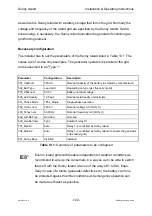
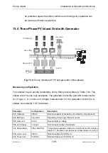
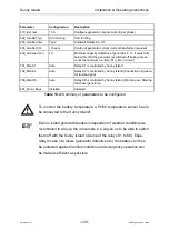
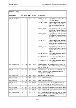
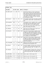
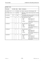
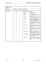
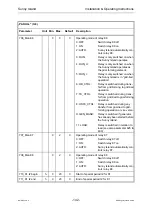
The installer has to set the parameters listed in Table 13.3. The values are of course
only examples. The generator is defined to be grid forming and is assumed to be of
type 2. A current and voltage measurement for the generator should be installed.
See chapter 3.4.5 for details.
Parameter Configuration
Description
501_Cbatnom
350 Ah
Nominal capacity of the battery (as stated by manufacturer)
502_Bat Type
Lead acid
Depending on type (gel, fleece or liquid)
503_Ubar nom
60.0 V
Nominal battery voltage
506_acid density
1.28 kg/l
Nominal acid density of electrolyte
401_Phase Mode
1Phs_Single
Single-phase operation
402_Uconv nom
230.0 V
Nominal voltage AC (RUN_U)
403_Fconv nom
50.00 Hz
Nominal frequency AC (RUN_U)
410_lext nom
10 A
Configure generator nominal current
602_GenSET typ
Grid forming
Grid-forming
603_GenSet inter
Typ 2
Relays K1+K5
604_GenSet Ctrl
I_Diesel
Control of generator current (current transformer required)
609_GenLoad min
10
Minimum generator capacity utilization in %, if value falls be-
low limit the generator is switched off (taking into account
the minimum run-time “613_tGen minrun“).
701_Man K1
Auto
Relay 1 is controlled by Sunny Island
702_Man K2
Auto
Relay K2 is controlled by Sunny Island (Connection of gen-
erator to island grid)
703_Man K3
Auto
Relay K3 is controlled by Sunny Island (Connection of ex-
ternal utility to island grid)
705_Man K5
Auto
Relay 5 is controlled by Sunny Island
706_Man K6
Auto
Relay K6 is controlled by Sunny Island (Warming up / Start-
ing the Diesel generator)
801_Sunny Boys
Installed
Installed
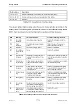
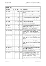
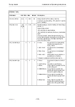
Table 13.3: Summary of parameters to be configured
Even in island grids with feeders independent of weather conditions we
recommend to wire up the consumers in a way so as to be able to switch
them off with the Sunny Island (via one of the relays K1 to K8). Espe-
cially in case of a failure (generator defective etc.) the battery can thus


