Sunny Island
Installation & Operating Instructions
BWRI33-12:EE
- 146 -
SMA Regelsysteme GmbH
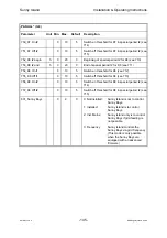
15 Overview: Measured Values Displayed
Name Unit
Min.
Max.
Default
Description
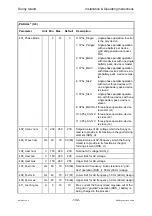
“DATSYS” (1-1)
SN:
Serial number of device
Vers:
Firmware versions of BFR and DSP
UP:
h
0.0
Counter of operating hours
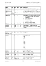
Name Unit
Min.
Max.
Default
Description
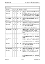
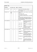
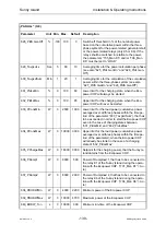
“DATALL” (1-2), Passwort-Level: 1
Status
0
13
0
Current operating state
0: INIT
Initialization
1: INIT
Initialization
2: STANDBY
Waiting state
3: SLAVE
Slave mode (three-phase ope-
ration)
4: STARTUP
Start
5: RUN_U
Inverter operation (island grid)
6: RUN_I
Charging operation on grid or
generator
7: GEN_MANU
man. start of generator
detected
8: HD_CTRL
Transfer from RUN_U to
RUN_I
9: TK_CTRL
Transfer from RUN_I to
RUN_U
10: SHUTDOWN Shutdown
11: ERRSHDWN Shutdown due to error
12: FAULT
Fault state
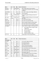
Batt. Ah In
Ah
0
0
0
Ah into the battery
Batt. Ah Out
Ah
0
0
0
Ah out of the battery
W in
kWh
0
0
0
Input power AC side
W out
kWh
0
0
0
Output power AC-side
Energy Count
h
0
0
0
Run-time of energy counter
Up Time
h
Time since switch-on (“Up-Time“)
Pconv Sum
kW
-320
320
0
Sum of grid active power SI (three phases)
Qconv Sum
kvar
-320
320
0
Sum of grid reactive power SI (three phases)
Sconv Sum
kVA
-320
320
0
Sum of grid apparent power SI (three phases)
Iconv Sum
A
0
640
0
Inverter current (three phases)
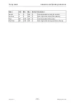
Pext Sum
kW
-320
320
0
Sum of generator active power (three phases)
Pext L1
kW
-320
320
0
Generator active power phase 1

