Sunny Island
Installation & Operating Instructions
BWRI33-12:EE
- 148 -
SMA Regelsysteme GmbH
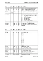
Name Unit
Min.
Max.
Default
Description
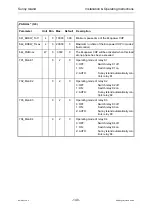
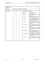
6=F_Stop
failure during stop (could not be
stopped)
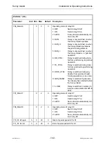
K1 State
0
1
0
State of relay
0=off
1=on
K2 State
0
1
0
State of relay
K3 State
0
1
0
State of relay
K4 State
0
1
0
State of relay
K5 State
0
1
0
State of relay
K6 State
0
1
0
State of relay
K7 State
0
1
0
State of relay
K8 State
0
1
0
State of relay
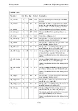
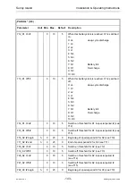
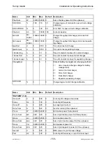
SB Step
%
-100
100
0
Current step size for Sunny Boy power limitation
Fext
Hz
0
100
0
Current grid frequency on synchronous input
Uext eff
V
0
500
0
RMS value of synchronous voltage
Iext eff
A
0
500
0
Current generator current (from converter)
Pext
kW
-320
320
0
Current generator active power
Ubat mean
V
0
200
0
Mean value of battery voltage
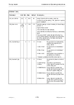
Ibat mean
A
-150
150
0
Mean value of battery current
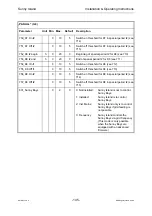
Pbat mean
W
-32000 32000 0
Mean value of battery power
Tbat mean
degC
-25
125
0
Mean value of battery temperature
Uzw Cuk mean
V
0
500
0
Mean value of the intermediate circuit voltage
Fconv
Hz
0
100
0
Current grid frequency
Uconv eff
V
0
500
0
Current grid voltage actual value
Iconv eff
A
0
320
0
RMS value of grid current
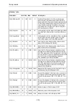
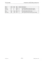
Pconv
W
-32000 32000 0
Grid active power Sunny Island
Sconv
VA
-32000 32000 0
Grid apparent power SI
Qconv
var
-32000 32000 0
Grid reactive power SI
Uchrg act
V
0
200
0
Setpoint value of battery voltage
Cbat act
Ah
50
10000
100
Current battery capacity
SOC diff AHB
%
0
100
50
Error of charge degree for full charge degree cali-
bration
Qdn full
Ah/
100Ah
-10000 10000 0
Charge throughput (discharge) since last full
charge
Qdn equal
Ah/
100Ah
-10000 10000 0
Charge throughput (discharge) since last equaliz-
ing charge
tpast full
d
0
3700
0
Time since last full charge
tpast equal
d
0
3700
0
Time since last equalizing charge

