Sunny Island Installation and Operating Instructions
BWRI33-12:EE
- 173 -
SMA Regelsysteme GmbH
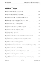
23 List of Figures
Fig. 2.1: Components of the battery inverter .............................................................13
Fig. 3.1: Mounting slide with fastening points............................................................19
Fig. 3.2: Side view of the Sunny Island with dimensions...........................................20
Fig. 3.3: Cable glands and terminals of the Sunny Island.........................................22
Fig. 3.4: Terminal strip of the Sunny Island ...............................................................23
Fig. 3.5: Connection of battery to the Sunny Island ..................................................27
Fig. 3.6: Connection of a temperature sensor ...........................................................28
Fig. 3.7: AC voltage connection ................................................................................29
Fig. 3.8: Connection of generator current and voltage measurement .......................30
Fig. 3.9: Power loss due to the secondary circuit to the inverter ...............................31
Fig. 3.10: Connection of a (diesel) generator ............................................................32
Fig. 3.11: Example of connection for an accelerated switch-over (generator)...........33
Fig. 3.12: Connection to an external utility ................................................................35
Fig. 3.13: Connection for an accelerated switch-over (utility) ....................................36
Fig. 3.14: Connection to generator and utility............................................................38
Fig. 3.15: Example of an accelerated switch-over (generator and utility) ..................39

