Sunny Island
Installation & Operating Instructions
BWRI33-12:EE
- 23 -
SMA Regelsysteme GmbH
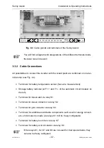
can also be freely configured.
The terminals K1 to K8 can only be used if they have been equipped
with their respective relays/modules optionally available.
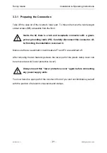
•
Terminals for the measurement of generator voltage and current
•
Grid connection (at F2:L and F2:N of the automatic circuit breaker as well as
at the PE terminals on the right)
AC Outlet
Fuse 16 A
Battery Input
Fuse 63 A
Battery
Temperature
X1:1 +RETURN
X1:2 +SEND
X1:3 -SEND
X1:4 -RETURN
X1:5 SHIELDING
X2:1/ -I
X2:2/+I
X2:3/ L
X2:4/ N
F1:+
F1:-
F2:L
F2:N
Diesel current
input
Diesel sync. input
K1:14
K1:13
Battery fan
Battery circulation
Diesel start
Diesel contactor
Control relay K3
Control relay K4
Control relay K5
Control relay K6
PE
PE
Chassis Earth
Chassis Earth
PE
PE
PE
PE
63 A
63 A
1
3
16 A
16 A
1
3
86-00742
0 - OFF
0 - OFF
K2:14
K2:13
K3:14
K3:13
K4:14
K4:13
K5:14
K5:13
K6:14
K6:13
K7:14
K7:13
K8:14
K8:13
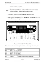
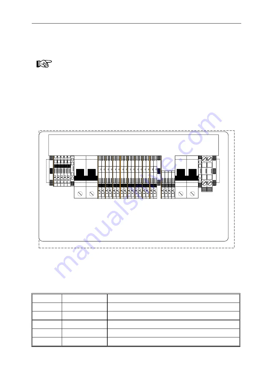
Fig. 3.4: Terminal strip of the Sunny Island
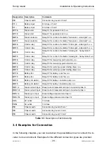
Table 3.1 shows the connector assignment on the terminal strip of the Sunny Island:
Designation Description
Comments
X1:1
Battery temperature + RETURN
X1:2
Battery temperature + SEND
X1:3
Battery temperature - SEND
X1:4
Battery temperature - RETURN
X1:5
Shielding
Possibility to connect shielding of sensor cable

