Sunny Island
Installation & Operating Instructions
BWRI33-12:EE
- 48 -
SMA Regelsysteme GmbH
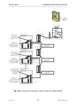
3.7.2 Multiple Connection at COM2 Interface
Chapter 13 describes the exemplary integration of feeders such as diesel generators
or block-type thermal power plants. To ensure fail-safe and troublefree establishment
of the communication connection please follow the instructions below:
Make sure there are termination resistors at the beginning and the end
of the RS485 bus. These can be activated either with jumpers within the
device, for the Sunny Boy Control alternatively with an external bridge
between pin 7 and pin 9 or with external resistors in the plug.
One of the devices on the RS485 bus has to be equipped with balancing
resistors. In the Sunny Boy Control these are already activated with
jumpers inside the device so that normally no additional measures have
to be taken.
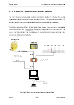
3.7.3 Simple Connection to PC
A PC is connected to a Sunny Island via RS232 with an ordinary serial data trans-
mission cable (modem elimination cable, SMA order name “SBCO-PC“).
If your PC is equipped with DB25 plugs or if only a DB25 plug is free (e. g. the COM1
DB9 plug is already used by a serial PC mouse) you additionally require a DB25/DB9
adapter (SMA order no. 36-5010).
You can also manufacture such a cable yourself following the description in the
manual for the Sunny Boy Control (chapter 3.2, PC interface). You will find this man-
ual on our website www.SMA.de for download.

