background image

9  Operation

SMA Solar Technology AG

Operating Manual

STPx0-3SE-40-BE-en-10

70

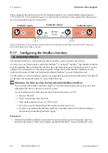
3. Enter the password in the field 

Password

.

4. Select 

Login

.

☑ The start page of the user interface opens.

Log Out as the User or Installer

1. On the right-hand side of the menu bar, select the menu 

User Settings

.

2. In the subsequent context menu, select [

Logout

].

☑ The login page of the user interface opens. The logout was successful.

Summary of Contents for SUNNY TRIPOWER 10.0 SMART ENERGY

Page 1: ...Operating Manual SUNNY TRIPOWER 5 0 6 0 8 0 10 0 SMART ENERGY STPx0 3SE 40 BE en 10 Version 1 0 ENGLISH...

Page 2: ...ot apply in all cases under some statutes and thus the above exclusion may not apply Specifications are subject to change without notice Every attempt has been made to make this document complete accu...

Page 3: ...Scope of Delivery 16 4 Product Overview 18 4 1 Product Description 18 4 2 Symbols on the Product 19 4 3 Interfaces and Functions 20 4 4 LED Signals 23 4 5 Battery Management 25 5 SMA Energy System Ho...

Page 4: ...dure 62 8 2 Commissioning the Inverter 63 8 3 Selecting a configuration option 63 9 Operation 66 9 1 Establishing a connection to the user interface 66 9 1 1 Establishing a Direct Connection via Ether...

Page 5: ...File 83 9 20 Adopting a Configuration from a File 83 9 21 Activating Automatic Firmware Update 84 9 22 Updating the Firmware 84 10 Disconnecting the Inverter from Voltage Sources 86 11 Clean the prod...

Page 6: ...allation and commissioning of electrical devices and installations Knowledge of all applicable laws standards and directives Knowledge of and compliance with this document and all safety information K...

Page 7: ...ut is not safety rele vant Indicates a requirement for meeting a specific goal Desired result A problem that might occur Example Sections describing activities to be performed by qualified persons onl...

Page 8: ...onnection Overview of approved batteries Technical Information PUBLIC CYBER SECURITY Guidelines for a Secure PV System Communication Technical Information SMA Smart Home The System Solution for Greate...

Page 9: ...e operated with PV modules whose frame is grounded The product must only be operated in connection with an intrinsically safe lithium ion battery approved by SMA Solar Technology AG An updated list of...

Page 10: ...stallation electrical safety and use of the product SMA Solar Technology AG assumes no responsibility for the compliance or non compliance with such laws or codes in connection with the installation o...

Page 11: ...y from voltage sources and make sure it cannot be reconnected before working on the device Observe all safety information of the battery manufacturer Do not touch non insulated parts or cables Do not...

Page 12: ...ork cables or other data cables if there is no surge protection Touching live parts and cables results in death or lethal injuries due to electric shock Ensure that all devices in the same network and...

Page 13: ...pair work when wearing personal protective equipment for handling of hazardous substances e g safety gloves eye and face protection respiratory protection WARNING Risk of injury due to toxic substance...

Page 14: ...ng devices with a DC input voltage range of 1000 V or higher CAUTION Risk of burns due to hot enclosure parts The enclosure and the enclosure lid may get hot during operation The DC load break switch...

Page 15: ...amage to the product due to cleaning agents The use of cleaning agents may cause damage to the product and its components Clean the product and all its components only with a cloth moistened with clea...

Page 16: ...pieces for Sunny Tripower 10 0 SE E 2 3 Negative DC connector 2 pieces for Sunny Tripower 5 0 SE 6 0 SE and 8 0 SE 3 pieces for Sunny Tripower 10 0 SE F 4 6 Sealing plug 4 pieces for Sunny Tripower 5...

Page 17: ...lock M 1 Quick reference guide with password label on the rear side The label contains the following information PIC Product Identification Code identification key for registering the system in Sunny...

Page 18: ...ec tion to the inverter s user interface via WLAN D Type label The type label clearly identifies the product The type label must remain per manently attached to the product You will find the following...

Page 19: ...ng time of 10 minutes High voltages that can cause lethal electric shocks are present in the live com ponents of the inverter Prior to performing any work on the inverter disconnect it from all voltag...

Page 20: ...ith the requirements of the applicable Australian stan dards The product complies with the Moroccan safety and EMC requirements for electronic products 4 3 Interfaces and Functions The product is equi...

Page 21: ...rters over several systems If there is an existing Wi Fi or Ethernet connection you can directly access your visualized system via the web browser on your smart device e g smartphone tablet or laptop...

Page 22: ...battery backup grid only when enough power is available in the battery Battery backup operation starts automatically as soon as enough energy is available from the PV system By setting parameters it...

Page 23: ...unny Portal and up to date 4 4 LED Signals The LEDs indicate the operating state of the product LED signal Explanation Green LED and red LED flash simultaneously 2 s on and 2 s off No country data set...

Page 24: ...ny Home Manager The blue LED flashes slowly for approx 1 minute Communication connection is being established The product is establishing a connection to a local network or is es tablishing a direct c...

Page 25: ...tage of bat tery charge to be retained for battery backup operation This battery charge can not be used in parallel grid operation even if the battery backup operation is deacti vated C Device Self co...

Page 26: ...SMA Energy System Home 5 1 System Components The Sunny Tripower Smart Energy is part of the SMA Energy System Home For more information on the SMA Energy System Home and the individual components see...

Page 27: ...0 C Battery A list of the approved batteries can be found in the technical information Approved Bat teries and Information on Battery Communication Connection at www SMA Solar com D Optional SMA EV Ch...

Page 28: ...SMA 360 APP SUNNY PORTAL Speedwire COM SUNNY HOME MANAGER 2 0 INTERNET SMA EV CHARGER UTILITY GRID PV MODULES BATTERY NON CONTROLLABLE LOADS Radio AC DC UTILITY METER FOR BILLING PURPOSES ROUTER CONTR...

Page 29: ...ergy PV1 BAT ETH AC GRID L3 L2 L1 N PE PV2 AC BACKUP L3 L2 L1 N PE ETH DC DC DC DC DC DC PE GRID CONNECTION POINT with energy meter of the electric utility company PROTECTIVE DEVICE UTILITY GRID Groun...

Page 30: ...CKUP L3 L2 L1 N PE ETH DC DC DC DC DC DC GRID CONNECTION POINT with energy meter of the electric utility company PROTECTIVE DEVICE UTILITY GRID Grounding conductor Line conductor Neutral conductor PRO...

Page 31: ...NNECTION POINT with energy meter of the electric utility company PROTECTIVE DEVICE UTILITY GRID Grounding conductor Line conductor Neutral conductor LOADS without backup HOUSE DISTRIBUTION BOARD with...

Page 32: ...3SE 40 BE en 10 32 5 4 Communication Overview SUNNY PORTAL SUNNY HOME MANAGER SMA ENERGY METER SUNNY TRIPOWER SMART ENERGY SMA Energy APP SMA 360 APP Public Internet SWITCH INTERNET ROUTER Radio BATTE...

Page 33: ...of the product see Section 16 page 122 The mounting location must not be exposed to direct solar irradiation If the product is exposed to direct solar irradiation the exterior plastic parts might age...

Page 34: ...ended clearances adequate heat dissipation will be ensured Thus you will prevent power reduction due to excessive temperature Maintain the recommended clearances to walls as well as to other inverters...

Page 35: ...surface and the screws CAUTION Risk of injury due to weight of product Injuries may result if the product is lifted incorrectly or dropped while being transported or mounted Transport and lift the pro...

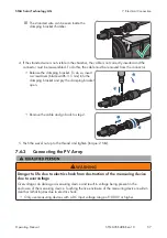
Page 36: ...is the 2 bolts on the right and left between the ribs on the back of the inverter must be hooked into the keyways of the wall mounting bracket 6 Ensure that the inverter is securely in place 7 Secure...

Page 37: ...1 positive and 1 negative DC connector for battery type Multi Contact MC4 connection D Network port with protective cap E Jack with protective cap for the WLAN antenna F CAN DIG I O socket with prote...

Page 38: ...m for information on how to select a residual current device Each inverter in the system must be connected to the utility grid via a separate residual current device Overvoltage category The product c...

Page 39: ...operator must be met The grid voltage must be within the permissible range The exact operating range of the inverter is specified in the operating parameters Procedure 1 Disconnect the AC and backup...

Page 40: ...mm 9 Strip the insulation of L1 L2 L3 N and the grounding conductor 12 mm 10 Insert the conductors L1 L2 L3 N and grounding conductor into the terminal block according to the labeling and tighten the...

Page 41: ...10 41 14 Remove the protective cap from the AC GRID socket 15 Insert the AC connector into the AC GRID socket The AC connector must snap audibly into place click 16 Slide the fuse terminal block onto...

Page 42: ...inverter disconnect it from all voltage sources as described in this document Ensure that the grounding conductors of the electric circuits of the battery backup appliances are connected to the groun...

Page 43: ...swivel nut and connector enclosure 9 Dismantle the AC cable 80 mm to 90 mm 10 Strip the insulation of L1 L2 L3 N and the grounding conductor 12 mm 11 Insert the conductors L1 L2 L3 N and grounding co...

Page 44: ...r into the AC BACKUP socket The AC connector must snap audibly into place click 18 Slide the fuse terminal block onto the bracket of the AC connector from the left and screw tight PH1 torque 0 5 Nm 2...

Page 45: ...tning can be further conducted into the building and to other connected devices in the same network via the network cables or other data cables if there is no surge protection Touching live parts and...

Page 46: ...Number of insulated conductor pairs and insulated conductor cross section at least 2 x 2 x 0 22 mm Maximum cable length between 2 nodes when using patch cables 50 m Maximum cable length between 2 nod...

Page 47: ...ant to connect the product to a communication product e g Energy Meter Sunny Home Manager connect a second network cable to the second network socket as described in this section Connect the other end...

Page 48: ...0 12 14 16 18 2 4 6 8 10 12 14 16 18 BMS CAN DI DO 11 13 15 17 11 13 15 17 11 13 15 17 Figure 14 PIN overview Pin Pin assignment BMS CAN 1 CAN H 2 Enable signal 3 CAN L 4 Enable ground 5 Not assigned...

Page 49: ...ched off 4 Unscrew the swivel nut from the threaded sleeve of the COM connector 5 Remove the terminal from the threaded sleeve 1 2 6 Connect the CAN communication cable see Section 7 5 3 page 50 7 Con...

Page 50: ...tery communication cable via CAN bus Additionally required material not included in the scope of delivery 1 battery communication cable for the communication between inverter and battery Bootlace ferr...

Page 51: ...the terminal Pay attention to the assignment of the terminal and communication connection on the battery and make sure that CAN L and CAN H consist of a pair of conductors For additional information...

Page 52: ...receiver Figure 15 Connection of a Ripple Control Receiver Procedure 1 Connect the connection cable to the digital signal source see the manual from manufacturer 2 Remove 1 sealing plug from the cabl...

Page 53: ...red material not included in the scope of delivery Connection cable Bootlace ferrules only for multi core stranded wire usable length of the ferrule at least 12 mm Requirements for connection cable Co...

Page 54: ...40 STP6 0 3SE 40 STP8 0 3SE 40 1 string can be connected to DC input A and 1 string can be connected to DC input B In case of STP10 0 3SE 40 1 string can be connected to DC input A and 2 strings to DC...

Page 55: ...on cables of the PV modules must be equipped with the negative DC connectors see Section 7 6 2 page 55 Use of Y adapters for parallel connection of strings The Y adapters must not be used to interrupt...

Page 56: ...described in the following The procedure is identical for both connectors and The graphics for the procedure are shown for only the positive connector as an example Pay attention to the correct polar...

Page 57: ...mm into the clamping bracket and pry the clamping bracket open 2 1 Remove the cable and go back to step 2 1 2 5 Push the swivel nut up to the thread and tighten torque 2 Nm 7 6 3 Connecting the PV Arr...

Page 58: ...operation Due to the transformerless topology of the product the occurrence of ground faults on DC side during operation can lead to irreparable damage Damages to the product due to a faulty or damag...

Page 59: ...roduct due to sand dust and moisture ingress if the DC inputs are not closed The product is only properly sealed when all unused DC inputs are closed with DC connectors and sealing plugs Sand dust and...

Page 60: ...ous injury due to electric shock Wear insulated gloves and use insulated tools when working on the DC connectors Ensure that the DC connectors are in perfect condition and that none of the DC conducto...

Page 61: ...eaning agents for cleaning the DC connectors Requirements Only use the supplied battery connection cables with DC connectors Alternatively MC4 connectors from St ubli can be used with battery connecti...

Page 62: ...he system The system password assigned via the communication device is also the password for the user interface of the inverter Commission the inverter see Section 8 2 page 63 The initial configuratio...

Page 63: ...ED starts to flash and if the inverter is connected via Speedwire the blue LED also starts to flash 4 If the green and red LEDs flash simultaneously during initial commissioning operation is stopped b...

Page 64: ...d D Checkbox Allows you to choose not to have the displayed page displayed again when the user interface is called up again E Configuration options Provides a selection of the various configuration op...

Page 65: ...ry 4 To correct settings you made select Back navigate to the desired step correct settings and select Save and continue 5 Once all settings are correct select Next in the summary 6 To save the settin...

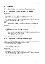
Page 66: ...een entered a message might appear indicating that the connection to the user interface of the product is not secure SMA Solar Technology AG guarantees the security of the user interface Continue load...

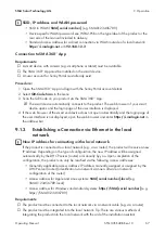
Page 67: ...gin page of the user interface is not displayed open the web browser and enter https smalogin net in the address bar 9 1 3 Establishing a Connection via Ethernet in the local network New IP address fo...

Page 68: ...s Depending on the type of configuration the new IP address will be assigned automatically by the DHCP server router or manually by you Upon completion of the configuration the product can only be rea...

Page 69: ...r password only pass the password on to persons to receive access to the system Installer password for inverters registered in a communication device or in Sunny Portal To be able to register the inve...

Page 70: ...in the field Password 4 Select Login The start page of the user interface opens Log Out as the User or Installer 1 On the right hand side of the menu bar select the menu User Settings 2 In the subsequ...

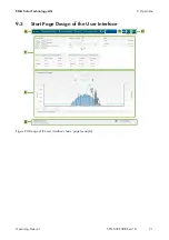
Page 71: ...9 Operation SMA Solar Technology AG Operating Manual STPx0 3SE 40 BE en 10 71 9 3 Start Page Design of the User Interface C B E F D A Figure 20 Design of the user interface s home page example...

Page 72: ...only the higher priority event is displayed If for example there is a Warning and an Error present at the same time only the Error will be displayed Device configuration Various settings for the inve...

Page 73: ...s display The various areas display information on the current status of the system Device status Displays whether the inverter is currently in a fault free operating state or whether there is an Erro...

Page 74: ...er Screen the most important inverter data is displayed directly on the user interface login page To activate the Smart Inverter Screen proceed as listed in the following Procedure 1 Activate the user...

Page 75: ...nstaller 3 Select the menu User Settings see Section 9 3 page 71 on the start page of the user interface 4 In the context menu select Starting the installation assistant The installation assistant wil...

Page 76: ...itched off completely the inverter must be connected to a computer or router via Ethernet Procedure To switch on the WLAN direct connection in the parameter group PV system communication WLAN select t...

Page 77: ...ring the Country Data Set For the product to begin operation a country data set must be set for instance via the installation assistant on the user interface of the product or via a communication prod...

Page 78: ...systems with manual setpoint 1 In the tab Active power mode set the switch Grid connection point regulation to On 2 Enter the total power of the PV array in the field Nominal system power 3 In the dr...

Page 79: ...et the values for the interpolation points 9 12 3 Setting the P f characteristic curve The characteristic curve is preset according to country data set You can make adjustments via parameter settings...

Page 80: ...s operating mode and the associated connection variant you will have to change the operating mode of the multifunction relay and make other settings if necessary The basic procedure for changing opera...

Page 81: ...el Grid Operation In parallel grid operation the backup loads can be supplied from the utility grid as long as the amperage and voltage of the backup loads circuits are within the permitted range If t...

Page 82: ...rotocols can be changed For information on commissioning and configuration of the Modbus interface see the technical information SMA and SunSpec Modbus Interface at www SMA Solar com For information o...

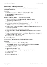
Page 83: ...the parameter SMA ShadeFix switched on to Off 9 19 Saving the Configuration in a File You can save the current configuration of the inverter in a file You can use this file as a data backup for this i...

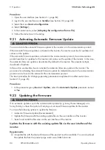
Page 84: ...e describe how to activate the automatic firmware update in the inverter The procedure for activating the automatic firmware update for detected devices in the communication product can be found in th...

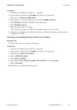
Page 85: ...rmware update is installed The installation takes about 15 minutes 8 Open the user interface and check the events to see whether the firmware update has been completed successfully Searching and updat...

Page 86: ...ent in the enclosure of the measuring device Touching the live enclosure of the measuring device results in death or lethal injuries due to electric shock Only use measuring devices with a DC input vo...

Page 87: ...onnectors Ensure that the DC connectors are in perfect condition and that none of the DC conductors or DC plug contacts are exposed Carefully release and remove the DC connectors as described in the f...

Page 88: ...battery connection cables and pull slightly to remove the DC connectors 1 2 13 Ensure that the AC connectors for connection to the utility grid and for connection of the AC backup loads are marked so...

Page 89: ...e the screw of the fuse terminal of the AC connector for connecting the utility grid PH1 and slide the fuse terminal to the left 2 1 17 Squeeze the tabs on the top and bottom of the AC connector for c...

Page 90: ...e product NOTICE Damage to the product due to cleaning agents The use of cleaning agents may cause damage to the product and its components Clean the product and all its components only with a cloth m...

Page 91: ...ten the password for the inverter you can unlock the inverter with a Personal Unlocking Key PUK For each inverter there is 1 PUK for each user group User and Installer Tipp With PV systems that are re...

Page 92: ...tly within the permissible range and this message is still displayed contact the Service 202 203 205 206 Grid incident The utility grid has been disconnected the AC cable is damaged or the grid voltag...

Page 93: ...meters with the Service 601 Grid incident The inverter has detected an excessively high proportion of direct current in the grid current Corrective measures Check the grid connection for direct curren...

Page 94: ...nverter If the DC voltage is below the maximum input voltage of the inverter reconnect the DC connectors to the inverter If the DC voltage exceeds the maximum input voltage of the inverter ensure that...

Page 95: ...ded Wait for higher irradiation If this message is displayed frequently in the morning increase the voltage limit for starting grid feed in Change the parameter Critical voltage to start feed in If th...

Page 96: ...sures Contact the Service 6501 6502 6509 Self diagnosis Overtemperature The inverter has switched off due to excessive temperature Corrective measures Ensure that the airflow is free of dirt Ensure th...

Page 97: ...ce 6603 6604 Self diagnosis Overload The cause must be determined by the Service Corrective measures Contact the Service 6607 6608 6609 6610 Self diagnosis Battery overcurrent Corrective measures Chec...

Page 98: ...asurement error Corrective measures Contact the Service 7106 Update file defective The update file is defective The update failed The inverter continues to feed in 7110 No update file found No new upd...

Page 99: ...e is suitable for this inverter If this message is displayed again contact the Service 7333 Update transport failed Update file could not be copied to the inverter s internal memory In the event of co...

Page 100: ...able for this inverter Retry import 7348 Incorrect file format The configuration file is not of the required format or is damaged Corrective measures Ensure that the selected configuration file is of...

Page 101: ...rective measures Ensure that the communication between SMA Backup Unit Controller and the inverter functions perfectly Ensure that the cable requirements of the communication cable for the communicati...

Page 102: ...Check communication to meter The inverter is not receiving any data from the energy meter Corrective measures Ensure that the energy meter is correctly integrated into the same network as the inverte...

Page 103: ...er 9308 Communication error battery system Corrective measures Carry out communication test If the test was successful contact the battery manufacturer If the test was not successful contact the Servi...

Page 104: ...e battery test for discharging the battery is carried out 9336 Start conditions for battery test not fulfilled The state of charge of the battery is too low or too high for carrying out the test Corre...

Page 105: ...351 Incorrect switch position for the battery disconnection point Corrective measures Contact the battery manufacturer 9352 Battery system short circuit Corrective measures Contact the battery manufac...

Page 106: ...e measures Increase the query intervals If necessary reduce the number of devices in the network 10249 Interface network overloaded The network is overloaded There is no data exchange between the devi...

Page 107: ...ta transfer rate has changed The cause for the status 10 Mbit can be a defective plug a defective cable or the pulling or plugging of the network connector Corrective measures if the status is 10 Mbit...

Page 108: ...After several incorrect login attempts login has been blocked for a limited time The user login will be locked for 15 minutes Corrective measures Wait until the given time has expired and then retry...

Page 109: ...tion has been enabled 10340 Webconnect disabled The Webconnect function has been disabled 10341 Webconnect error no connection It is likely that there is an error in the network settings Corrective me...

Page 110: ...r ied sma de 9523 Proxy ied sma de 9523 Stun stun sma de 3478 Domain ied sma de for SIP URI 10352 Webconnect error Faulty communication It is likely that there is an error in the network settings or a...

Page 111: ...er does not respond to active power limitation 10528 Login for NSD function on device s0 failed 27107 Update file OK The update file found is valid 27108 Memory card is being read The storage medium i...

Page 112: ...s connected Disconnect the loads from the electric circuit 12 3 Checking the PV System for Ground Faults If the red LED is glowing and the event number 3501 3601 or 3701 is being displayed in the Resu...

Page 113: ...ed as follows to check each string in the PV system for ground faults Procedure 1 DANGER Danger to life due to high voltages Disconnect the inverter from all voltage sources see Section 10 page 86 2 M...

Page 114: ...nd fault between the second and third PV module 100 V 100 V 100 V 100 V 100 V V 200 V 1 V 300 V 2 Test by Measuring the Insulation Resistance If the voltage measurement does not provide sufficient evi...

Page 115: ...of the PV array The insulation resistance can only be measured with a suitable device for safe disconnection and short circuiting of the PV array If no suitable device is available the insulation meas...

Page 116: ...les might not be suitable for the inverter in the present quantity 12 4 Problems with streaming services If you use the streaming service in your local network in which the inverter is also included t...

Page 117: ...duct carefully Take the weight of the product into account Always have two persons mount and disassemble the product Wear suitable personal protective equipment for all work on the product Procedure 1...

Page 118: ...vel nut from the threaded sleeve 13 Remove the terminal from the threaded sleeve 1 2 14 Remove all conductors from the terminal points using a screwdriver blade width 2 5 mm 1 2 15 Put the protective...

Page 119: ...screws for fastening the wall mounting bracket and remove the wall mounting bracket 21 If the inverter is to be stored or shipped pack the inverter the AC connectors the DC connectors the antenna the...

Page 120: ...ion 7 7 page 61 and see Section 7 5 3 page 50 3 Recommission the inverter see Section 8 2 page 63 4 Open the user interface see Section 9 1 page 66 5 Log in as Installer 6 Start the installation assis...

Page 121: ...ement device as described below Procedure 1 Decommission the defective product see Section 13 page 117 2 Mount the replacement device see Section 6 page 33 and make the electrical connections see Sect...

Page 122: ...ounding conductor 220 V 380 V 3 N grounding conductor 230 V 400 V 3 N grounding conductor 240 V 415 V 3 N grounding conductor 220 V 380 V 3 N grounding conductor 230 V 400 V 3 N grounding conductor 24...

Page 123: ...S TT if UN_ PE 20 V TN C TN S TN C S TT if UN_ PE 20 V Surge category in accordance with IEC 60664 1 III III III III DC input of PV STP5 0 3SE 40 STP6 0 3SE 40 STP8 0 3SE 40 STP10 0 3SE 40 Maximum pow...

Page 124: ...er MPP input A 1 B 1 A 1 B 1 A 1 B 1 A 1 B 2 Surge category in accordance with IEC 62109 1 II II II II DC output of battery STP5 0 3SE 40 STP6 0 3SE 40 STP8 0 3SE 40 STP10 0 3SE 40 Maximum DC volt age...

Page 125: ...W 12000 W Output apparent power 10 s 10000 VA 10000 VA 12000 VA 12000 VA Nominal AC volt age 3 N grounding conductor 230 V 400 V 3 N grounding conductor 230 V 400 V 3 N grounding conductor 230 V 400...

Page 126: ...gree outside the inverter 3 Pollution degree inside the inverter 2 Operating temperature range 25 C to 60 C Max permissible value for relative humidity condensing 100 Maximum operating altitude above...

Page 127: ...C to 70 C Storage temperature 40 C to 60 C Equipment DC terminal for PV SUNCLIX DC connection for battery MC4 AC terminal AC connector Battery communication CAN bus Speedwire interface As standard We...

Page 128: ...urrent 1 0 A Minimum load 0 1 W Minimum electrical endurance when the maxi mum switching voltage and maximum switching current are complied with3 100000 switching cycles Efficiency STP5 0 3SE 40 STP6...

Page 129: ...he necessary assistance Device type Serial number Firmware version Event message Mounting location and mounting height Type and number of PV modules Use the name of the system in Sunny Portal if avail...

Page 130: ...153 62 RED Restriction of the use of certain hazardous substances 2011 65 EU L 174 88 June 8 2011 and 2015 863 EU L 137 10 March 31 2015 RoHS SMA Solar Technology AG confirms herewith that the product...

Page 131: ...ons 2017 SI 2017 1206 The Restriction of the Use of Certain Hazardous Substances in Electrical and Electronic Equipment Regulations 2012 SMA Solar Technology AG confirms herewith that the products des...

Page 132: ...www SMA Solar com...

Reviews: