7 Electrical Connection
SMA Solar Technology AG
Operating Manual
STPx0-3SE-40-BE-en-10
51
Procedure:
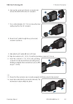
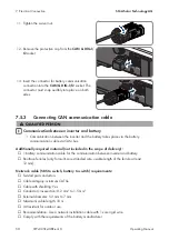
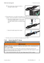
1. Remove 1 sealing plug from the cable support sleeve.
2. Lead the communication cable through the swivel
nut and threaded sleeve.
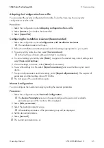
3. Strip the communication cable 40 mm to 50 mm.
4. Trim the cable shield to a length of 15 mm and fold
it over the cable sheath.
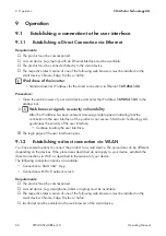
5. Strip the insulation on the insulated conductors each by 12 mm. The
CAN L
and
CAN H
must
be a twisted pair.
6. If necessary, trim unused insulated conductors flush with the cable sheath or fold it over the
cable sheath.
7. When using a multi-core stranded wire, provide the conductors with bootlace ferrules.
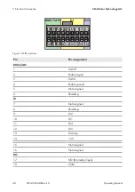
8. Connect the conductors of the communication cables to the terminal. Pay attention to the
assignment of the terminal and communication connection on the battery and make sure that
CAN L
and
CAN H
consist of a pair of conductors. For additional information on how to
connect the battery, see technical information "Approved Batteries and Information on Battery
Communication Connection" at www.SMA-Solar.com.
7.5.4
Connecting Signal Source to Digital Input
It is possible to connect a digital signal source (e.g. ripple control receiver or remote terminal unit)
to the digital input of the product. This must be connected if it is prescribed by the grid operator.
Additionally required material (not included in the scope of delivery):
☐ Connection cable
☐ Bootlace ferrules (only for multi-core stranded wire, usable length of the ferrule at least
12 mm)
Requirements for connection cable:
• Cable with shielding: Yes
• Conductor cross-section: 0.2 mm² to 1.5 mm²
• External diameter: 5.3 mm to 7 mm
Summary of Contents for SUNNY TRIPOWER 10.0 SMART ENERGY
Page 132: ...www SMA Solar com...


