7 Electrical Connection
SMA Solar Technology AG
Operating Manual
STPx0-3SE-40-BE-en-10
53
7.5.5
Connecting the Multifunction Relay
7.5.5.1 Procedure for connecting the multifunction relay
Procedure
See
1.
Select for which operating mode you would like to use the
multifunction relay.
2.
Connect to the multifunction relay according to the operat-
ing mode.
3.
After commissioning the inverter, change the operating
mode of the multifunction relay, if necessary.
7.5.5.2 Connection to the Multifunction Relay
Additionally required material (not included in the scope of delivery):
• Connection cable
• Bootlace ferrules (only for multi-core stranded wire, usable length of the ferrule at least
12 mm)
Requirements for connection cable:
• Conductor cross-section: 0.2 mm² to 1.5 mm²
• External diameter: 5.3 mm to 7 mm
• UV-resistant for outdoor use.
Procedure:
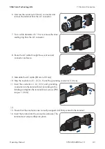
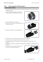
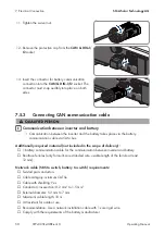
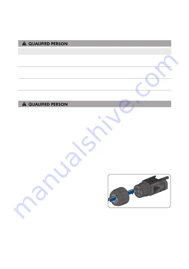
1. Remove 1 sealing plug from the cable support sleeve.
2. Lead the connection cable into the threaded sleeve.
3. Dismantle the connection cable 40 mm to 50 mm.
4. Strip the insulation on the insulated conductors each by 12 mm.
5. When using a multi-core stranded wire, provide the conductors with bootlace ferrules.
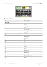
6. Connect the connection cable to the digital output of the inverter according to the assignment
of the terminal block of the COM connector (see Section 7.5.1, page 47).
Summary of Contents for SUNNY TRIPOWER 10.0 SMART ENERGY
Page 132: ...www SMA Solar com...

