☐ The connection requirements of the grid operator must be met.
☐ The grid voltage must be within the permissible range. The exact operating range of the
inverter is specified in the operating parameters.
Procedure:
1.
Danger to life due to electric shock
• Ensure that the three-pole circuit breaker is switched off and cannot be reconnected.
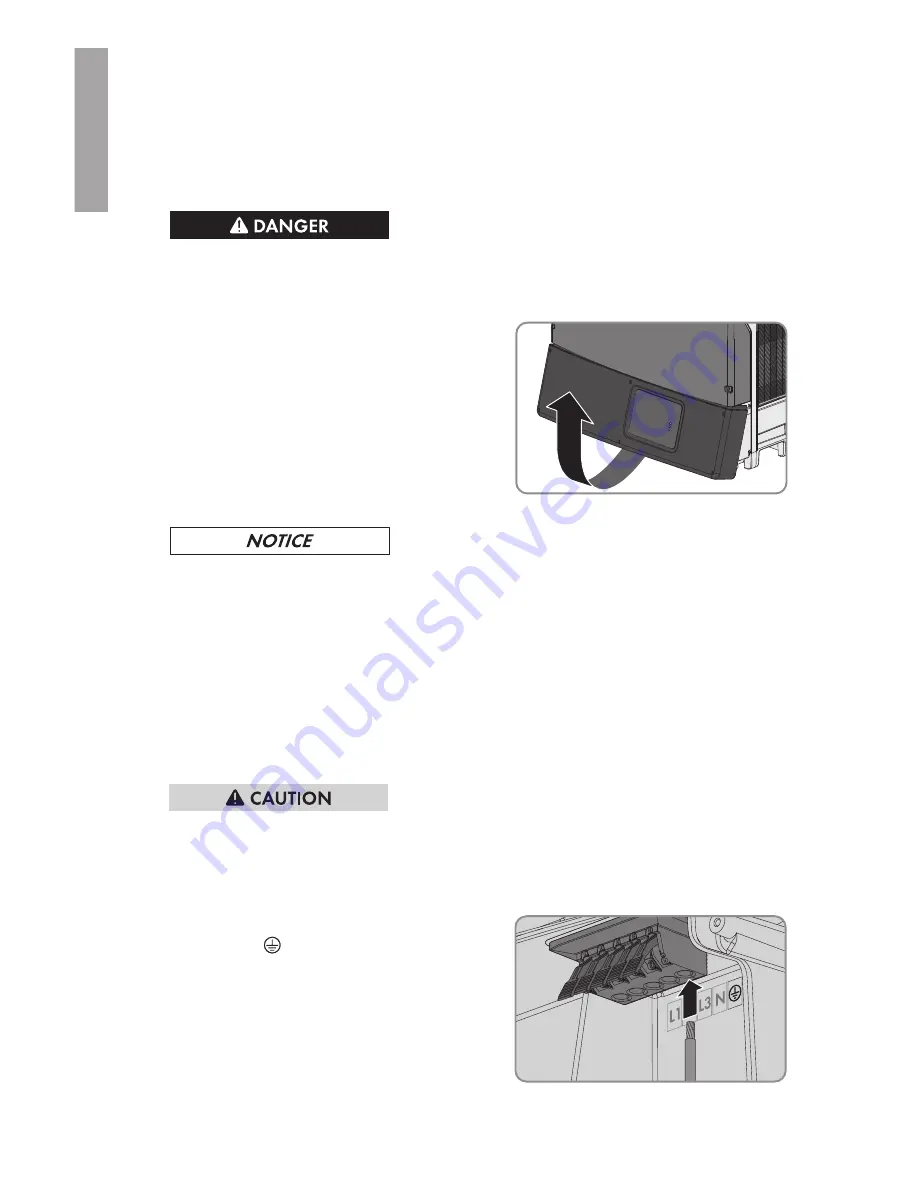
2. Release all screws of the lower enclosure lid using an Allen key (AF 3).
3. Lift and remove the lower enclosure lid from
below.
4. Remove the adhesive tape from the enclosure opening for the AC connection.
5.
Damage to the inverter due to moisture and dust intrusion
Electronic components in the inverter can be destroyed or damaged as a result of dust or
moisture intrusion.
• Do not enlarge the enclosure opening.
6. Insert the conduit fitting into the opening and tighten from the inside using the counter nut.
7. Attach the conduit to the enclosure opening.
8. Insert the AC cable through the conduit into the inverter.
9. Strip the cable insulation by 12 mm to 13 mm (0.5 in).
10. Open all locking levers of the connecting terminal plate right up to the stop.
11.
Risk of fire if two conductors are connected to one terminal
If you connect two conductors to a terminal, a fire can occur due to a bad electrical
connection.
• Never connect more than one conductor per terminal.
12. Connect the equipment grounding conductor to
the terminal
.
6 Electrical Connection
SMA Solar Technology America LLC
Installation Manual
STPTL-US-10-IA-xx-17
28
ENGLISH
Summary of Contents for SUNNY TRIPOWER 12000TL-US
Page 232: ...www SMA America com ...


